- Home
- Careers
- Contact
- About
-
Who we are and what we do. -
Press releases, announcements, and notable corporate information. -
We are looking for a few A people. -
We have over 40 years of innovation to create value for our customers. -
We aim to be the highest value provider of every product and service we offer. -
An easy guide to Probe fundamentals.
-
- Services
-
In additional to the analytical results we normally include an expert analysts summary.
We use our decades of experience to help you better understand your data. -
CleanAir can insures that the project goals and testing are objectives are met.
-
We can ship what you need today. It will work. You get a company of experts when you rent from CleanAir. - Thermal Performance
-
- Rental
-
Our factory reconditioning experts work to make old as good as new. -
CleanAir can provide the services required to care of your emissions measurement or power measurement instruments, no matter the age, model or manufacturer.
-
We deliver rental, emergency, or supplemental instruments and onsite services quickly, with minimal operational interruptions .
-
- Products
Featured Product

UL Listed Mobile Temporary Power
Look professional. Don't risk a OSHA fine, or worse causing your customer to get an OSHA or MSHA fine by using an unsafe mobile power distribution system. The CleanAir Temporary Power cart is UL listed! Read more... -
Reference
-
Overviews of products and services -
Learn about our companies and business -
Detailed technical information about the functioning of our products -
Guides and instructions on proper installation and service -
Guides and instructions on proper installation and service -
Drawings, configuration, materials, and limits useful for the planning and layout.
-
CleanAir's reference of video content -
Publications addressing an issue or topic
-
- Site Map
 Express
 FTIR
FTIR Mercury
 Emission Sampling Equipment
 Instrument Rental
EPA Methods List with Links
US EPA Method 5h - Determination Of Particulate Matter Emissions From Wood Heaters From A Stack Location
NOTE: This method does not include all of the specifications (e.g., equipment and supplies) and procedures (e.g., sampling and analytical) essential to its performance. Some material is incorporated by reference from other methods in this part. Therefore, to obtain reliable results, persons using this method should have a thorough knowledge of at least the following additional test methods: Method 2, Method 3, Method 5, Method 5G, Method 6, Method 6C, Method 16A, and Method 28.
1.0 Scope and Application.
1.1 Analyte. Particulate matter (PM).
No CAS number assigned.
1.2 Applicability.
This method is applicable for the determination of PM and condensible emissions from wood heaters.
1.3 Data Quality Objectives.
Adherence to the requirements of this method will enhance the quality of the data obtained from air pollutant sampling methods.
2.0 Summary of Method.
2.1 Particulate matter is withdrawn proportionally from the wood heater exhaust and is collected on two glass fiber filters separated by impingers immersed in an ice water bath. The first filter is maintained at a temperature of no greater than 120 C (248 F). The second filter and the impinger system are cooled such that the temperature of the gas exiting the second filter is no greater than 20 C (68 F). The particulate mass collected in the Probe, on the filters, and in the impingers is determined gravimetrically after the removal of uncombined water.
3.0 Definitions.
Same as in Method 6C, Section 3.0.
4.0 Interferences. [Reserved]
5.0 Safety.
5.1 Disclaimer.
This method may involve hazardous materials, operations, and equipment. This test method may not address all of the safety problems associated with its use. It is the responsibility of the user of this test method to establish appropriate safety and health practices and to determine the applicability of regulatory limitations prior to performing this test method.
6.0 Equipment and Supplies.
6.1 Sample Collection.
The following items are required for sample collection:
6.1.1 Sampling train.
The sampling train configuration is shown in Figure 5H-1. Same as Method 5, Section 6.1.1, with the exception of the following:
6.1.1.1 Probe probe nozzle.
The probe nozzle is optional; a straight sampling Probe without a probe nozzle is an acceptable alternative.
6.1.1.2 Probe liner.
Same as Method 5, Section 6.1.1.2, except that the maximum length of the sample Probe shall be 0.6 m (2 ft) and Probe heating is optional.
6.1.1.3 filter Holders.
Two each of borosilicate glass, with a glass frit or stainless steel filter support and a silicone rubber, Teflon, or Viton gasket. The holder design shall provide a positive seal against leakage from the outside or around the filter. The front filter holder shall be attached immediately at the outlet of the Probe and prior to the first impinger. The second filter holder shall be attached on the outlet of the third impinger and prior to the inlet of the fourth (silica gel) impinger.
6.1.2 barometer.
Same as Method 5, Section 6.2.
6.1.3 Stack Gas flow Rate Measurement System.
A schematic of an example test system is shown in Figure 5H-2. The flow rate measurement system consists of the following components:
6.1.3.1 Sample Probe.
A glass or stainless steel sampling Probe.
6.1.3.2 Gas Conditioning System.
A high density filter to remove particulate matter and a condenser capable of lowering the dew point of the gas to less than 5 C (40 F). Desiccant, such as Drierite, may be used to dry the sample gas. Do not use silica gel.
6.1.3.3 pump.
An inert (e.g., Teflon or stainless steel heads) sampling pump capable of delivering more than the total amount of sample required in the manufacturer's instructions for the individual instruments. A means of controlling the analyzer flow rate and a device for determining proper sample flow rate (e.g., precision rotameter, pressure gauge downstream of all flow controls) shall be provided at the analyzer. The requirements for measuring and controlling the analyzer flow rate are not applicable if data are presented that demonstrate that the analyzer is insensitive to flow variations over the range encountered during the test.
6.1.3.4 Carbon Monoxide (CO) Analyzer.
Any analyzer capable of providing a measure of CO in the range of 0 to 10 percent by volume at least once every 10 minutes.
6.1.3.5 Carbon Dioxide (CO2) Analyzer.
Any analyzer capable of providing a measure of CO2 in the range of 0 to 25 percent by volume at least once every 10 minutes.
NOTE: Analyzers with ranges less than those specified above may be used provided actual concentrations do not exceed the range of the analyzer.
6.1.3.6 Manifold.
A sampling tube capable of delivering the sample gas to two analyzers and handling an excess of the total amount used by the analyzers. The excess gas is exhausted through a separate port.
6.1.3.7 Recorders (optional).
To provide a permanent record of the analyzer outputs.
6.1.4 Proportional Gas flow Rate System.
To monitor stack flow rate changes and provide a measurement that can be used to adjust and maintain particulate sampling flow rates proportional to the stack gas flow rate. A schematic of the proportional flow rate system is shown in Figure 5H-2 and consists of the following components:
6.1.4.1 Tracer Gas Injection System.
To inject a known concentration of sulfur dioxide (SO2) into the flue. The tracer gas injection system consists of a cylinder of SO2, a gas cylinder regulator, a stainless steel needle valve or flow controller, a nonreactive (stainless steel and glass) rotameter, and an injection loop to disperse the SO2 evenly in the flue.
6.1.4.2 Sample Probe.
A glass or stainless steel sampling Probe.
6.1.4.3 Gas Conditioning System.
A combustor as described in Method 16A, Sections 6.1.5 and 6.1.6, followed by a high density filter to remove particulate matter, and a condenser capable of lowering the dew point of the gas to less than 5 C (40 F). Desiccant, such as Drierite, may be used to dry the sample gas. Do not use silica gel.
6.1.4.4 pump.
Same as described in Section 6.1.3.3.
6.1.4.5 SO2 Analyzer.
Any analyzer capable of providing a measure of the SO2 concentration in the range of 0 to 1,000 ppm by volume (or other range necessary to measure the SO2 concentration) at least once every 10 minutes.
6.1.4.6 Recorder (optional).
To provide a permanent record of the analyzer outputs.
NOTE: Other tracer gas systems, including helium gas systems, are acceptable for determination of instantaneous proportional sampling rates.
6.2 sample recovery.
Same as Method 5, Section 6.2.
6.3 Sample Analysis.
Same as Method 5, Section 6.3, with the addition of the following:
6.3.1 Separatory Funnel.
glass or Teflon, 500-ml or greater.
7.0 Reagents and Standards.
7.1 Sample Collection.
Same as Method 5, Section 7.1, including deionized distilled water.
7.2 sample recovery.
Same as Method 5, Section 7.2.
7.3 Sample Analysis.
The following reagents and standards are required for sample analysis:
7.3.1 Acetone.
Same as Method 5 Section 7.2.
7.3.2 Dichloromethane (Methylene Chloride).
Reagent grade, <0.001 percent residue in glass bottles.
7.3.3 Desiccant.
Anhydrous calcium sulfate, calcium chloride, or silica gel, indicating type.
7.3.4 Cylinder Gases.
For the purposes of this procedure, span value is defined as the upper limit of the range specified for each analyzer as described in Section 6.1.3.4 or 6.1.3.5 If an analyzer with a range different from that specified in this method is used, the span value shall be equal to the upper limit of the range for the analyzer used (see NOTE in Section 6.1.3.5).
7.3.4.1 calibration Gases.
The calibration gases for the CO2, CO, and SO2 analyzers shall be CO2 in nitrogen (N2), CO in N2, and SO2 in N2, respectively. CO2 and CO calibration gases may be combined in a single cylinder. Use three calibration gases as specified in Method 6C, Sections 7.2.1 through 7.2.3.
7.3.4.2 SO2 Injection Gas.
A known concentration of SO2 in N2. The concentration must be at least 2 percent SO2 with a maximum of 100 percent SO2.
8.0 Sample Collection, Preservation, Transport, and Storage.
8.1 Pretest Preparation.
Same as Method 5, Section 8.1.
8.2 calibration Gas and SO2 Injection Gas Concentration Verification, Sampling System Bias Check, Response Time Test, and Zero and calibration Drift Tests.
Same as Method 6C, Sections 8.2.1, 8.2.3, 8.2.4, and 8.5, respectively, except that for verification of CO and CO2 gas concentrations, substitute Method 3 for Method 6.
8.3 Preliminary Determinations.
8.3.1 Sampling Location.
The sampling location for the particulate sampling Probe shall be 2.45 ± 0.15 m (8 ± 0.5 ft) above the platform upon which the wood heater is placed (i.e., the top of the scale).
8.3.2 Sampling Probe and probe nozzle.
Select a probe nozzle, if used, sized for the range of velocity heads, such that it is not necessary to change the probe nozzle size in order to maintain proportional sampling rates. During the run, do not change the probe nozzle size. Select a suitable Probe liner and Probe length to effect minimum blockage.
8.4 Preparation of Particulate Sampling train.
Same as Method 5, Section 8.3, with the exception of the following:
8.4.1 The train should be assembled as shown in Figure 5H-1.
8.4.2 A glass cyclone may not be used between the Probe and filter holder.
8.5 Leak-Check Procedures.
8.5.1 Leak-Check of metering System Shown in Figure 5H-1.
That portion of the sampling train from the pump to the orifice meter shall be leak-checked after each certification or audit test. Use the procedure described in Method 5, Section 8.4.1.
8.5.2 Pretest Leak-Check.
A pretest leak-check of the sampling train is recommended, but not required. If the pretest leak-check is conducted, the procedures outlined in Method 5, Section 8.5.2 should be used. A vacuum of 130 mm Hg (5 in. Hg) may be used instead of 380 mm Hg (15 in. Hg).
8.5.2 Leak-Checks During Sample Run.
If, during the sampling run, a component (e.g., filter assembly or impinger) change becomes necessary, conduct a leak-check as described in Method 5, Section 8.4.3.
8.5.3 Post-Test Leak-Check.
A leak-check is mandatory at the conclusion of each sampling run. The leak- check shall be performed in accordance with the procedures outlined in Method 5, Section 8.4.4, except that a vacuum of 130 mm Hg (5 in. Hg) or the greatest vacuum measured during the test run, whichever is greater, may be used instead of 380 mm Hg (15 in. Hg).
8.6 Tracer Gas Procedure.
A schematic of the tracer gas injection and sampling systems is shown in Figure 5H-2.
8.6.1 SO2 Injection Probe.
Install the SO2 injection Probe and dispersion loop in the stack at a location 2.9 ± 0.15 m (9.5 ± 0.5 ft) above the sampling platform.
8.6.2 SO2 Sampling Probe.
Install the SO2 sampling Probe at the centroid of the stack at a location 4.1 ± 0.15 m (13.5 ± 0.5 ft) above the sampling platform.
8.7 flow Rate Measurement System.
A schematic of the flow rate measurement system is shown in Figure 5H-2. Locate the flow rate measurement sampling Probe at the centroid of the stack at a location 2.3 ± 0.3 m (7.5 ± 1 ft) above the sampling platform.
8.8 Tracer Gas Procedure.
Within 1 minute after closing the wood heater door at the start of the test run (as defined in Method 28, Section 8.8.1), meter a known concentration of SO2 tracer gas at a constant flow rate into the wood heater stack. Monitor the SO2 concentration in the stack, and record the SO2 concentrations at 10-minute intervals or more often. Adjust the particulate sampling flow rate proportionally to the SO2 concentration changes using Equation 5H-6 (e.g., the SO2 concentration at the first 10-minute reading is measured to be 100 ppm; the next 10 minute SO2 concentration is measured to be 75 ppm: the particulate sample flow rate is adjusted from the initial 0.15 cfm to 0.20 cfm). A check for proportional rate variation shall be made at the completion of the test run using Equation 5H-10.
8.9 Volumetric flow Rate Procedure.
Apply stoichiometric relationships to the wood combustion process in determining the exhaust gas flow rate as follows:
8.9.1 Test Fuel Charge Weight.
Record the test fuel charge weight (wet) as specified in Method 28, Section 8.8.2. The wood is assumed to have the following weight percent composition: 51 percent carbon, 7.3 percent hydrogen, 41 percent oxygen. Record the wood moisture for each fuel charge as described in Method 28, Section 8.6.5. The ash is assumed to have negligible effect on associated C, H, and O concentrations after the test burn.
8.9.2 Measured Values.
Record the CO and CO2 concentrations in the stack on a dry basis every 10 minutes during the test run or more often. Average these values for the test run. Use as a mole fraction (e.g., 10 percent CO2 is recorded as 0.10) in the calculations to express total flow (see Equation 5H-6).
8.10 Sampling train Operation.
8.10.1 For each run, record the data required on a data sheet such as the one shown in Figure 5H-3. Be sure to record the initial console meter reading. Record the console meter readings at the beginning and end of each sampling time increment, when changes in flow rates are made, before and after each leak-check, and when sampling is halted. Take other readings as indicated on Figure 5H-3 at least once each 10 minutes during the test run.
8.10.2 Remove the probe nozzle cap, verify that the filter and Probe heating systems are up to temperature, and that the Probe is properly positioned. Position the probe nozzle, if used, facing into gas stream, or the Probe tip in the 50 mm (2 in.) centroidal area of the stack.
8.10.3 Be careful not to bump the Probe tip into the stack wall when removing or inserting the Probe through the porthole; this minimizes the chance of extracting deposited material.
8.10.4 When the Probe is in position, block off the openings around the Probe and porthole to prevent unrepresentative dilution of the gas stream.
8.10.5 Begin sampling at the start of the test run as defined in Method 28, Section 8.8.1, start the sample pump>, and adjust the sample flow rate to between 0.003 and 0.014 m3/min (0.1 and 0.5 cfm). Adjust the sample flow rate proportionally to the stack gas flow during the test run according to the procedures outlined in Section 8. Maintain a proportional sampling rate (within 10 percent of the desired value) and a filter holder temperature no greater than 120 C (248 F).
8.10.6 During the test run, make periodic adjustments to keep the temperature around the filter holder at the proper level. Add more ice to the impinger box and, if necessary, salt to maintain a temperature of less than 20 C (68 F) at the condenser/silica gel outlet.
8.10.7 If the pressure drop across the filter becomes too high, making proportional sampling difficult to maintain, either filter may be replaced during a sample run. It is recommended that another complete filter assembly be used rather than attempting to change the filter itself. Before a new filter assembly is installed, conduct a leak-check (see Section 8.5.2). The total particulate weight shall include the summation of all filter assembly catches. The total time for changing sample train components shall not exceed 10 minutes. No more than one component change is allowed for any test run.
8.10.8 At the end of the test run, turn off the coarse adjust valve, remove the Probe and probe nozzle from the stack, turn off the pump, record the final console meter reading, and conduct a post-test leak-check, as outlined in Section 8.5.3.
8.11 sample recovery.
Same as Method 5, Section 8.7, with the exception of the following:
8.11.1 Blanks.
The volume of the acetone blank may be about 50-ml, rather than 200-ml; a 200-ml water blank shall also be saved for analysis.
8.11.2 Samples.
8.11.2.1 Container Nos. 1 and 1A.
Treat the two filters according to the procedures outlined in Method 5, Section 8.7.6.1. The filters may be stored either in a single container or in separate containers.
8.11.2.2 Container No. 2.
Same as Method 5, Section 8.7.6.2, except that the container should not be sealed until the impinger rinse solution is added (see Section 8.10.2.4).
8.11.2.3 Container No. 3.
Treat the impingers as follows: Measure the liquid which is in the first three impingers to within 1-ml by using a graduated cylinder or by weighing it to within 0.5 g by using a balance (if one is available). Record the volume or weight of liquid present. This information is required to calculate the moisture content of the effluent gas. Transfer the water from the first, second, and third impingers to a glass container. Tighten the lid on the sample container so that water will not leak out.
8.11.2.4 Rinse impingers and graduated cylinder, if used, with acetone three times or more. Avoid direct contact between the acetone and any stopcock grease or collection of any stopcock grease in the rinse solutions. Add these rinse solutions to sample Container No. 2.
8.11.2.5 Container No. 4.
Same as Method 5, Section 8.7.6.3
8.12 Sample Transport.
Whenever possible, containers should be transferred in such a way that they remain upright at all times.
NOTE: Requirements for capping and transport of sample containers are not applicable if sample recovery and analysis occur in the same room.
9.0 Quality Control.
9.1 Miscellaneous Quality Control Measures.
| Section | Quality Control Measure | Effect |
| 8.2 | Sampling system bias check. | Ensures that bias introduced by measurement system, minus analyzer, is no greater than 3 percent of span. |
| 8.2 | Analyzer zero and calibration drift tests. | Ensures that bias introduced by drift in the measurement system output during the run is no greater than 3 percent of span. |
| 8.5, 10.1, 12.13 | Sampling equipment leak-check and calibration; proportional sampling rate verification | Ensures accurate measurement of stack gas flow rate, sample volume |
| 10.1 | Analytical balance calibration | Ensure accurate and precise measurement of collected particulate |
| 10.3 | Analyzer calibration error check. | Ensures that bias introduced by analyzer calibration error is no greater than 2 percent of span. |
9.2 Volume metering System Checks.
Same as Method 5, Section 9.2.
10.0 Calibration and Standardization.
NOTE: Maintain a laboratory record of all calibrations.
10.1 Volume metering System, tenperature sensors, barometer, and Analytical Balance.
Same as Method 5G, Sections 10.2 through 10.5, respectively.
10.2 SO2 Injection Rotameter.
Calibrate the SO2 injection rotameter system with a soap film flowmeter or similar direct volume measuring device with an accuracy of 2 percent. Operate the rotameter at a single reading for at least three calibration runs for 10 minutes each. When three consecutive calibration flow rates agree within 5 percent, average the three flow rates, mark the rotameter at the calibrated setting, and use the calibration flow rate as the SO2 injection flow rate during the test run. Repeat the rotameter calibration before the first certification test and semiannually thereafter.
10.3. gas analyzers.
Same as Method 6C, Section 10.0.
11.0 Analytical Procedure.
11.1 Record the data required on a sheet such as the one shown in Figure 5H-4.
11.2 Handle each sample container as follows:
11.2.1 Container Nos. 1 and 1A.
Treat the two filters according to the procedures outlined in Method 5, Section 11.2.1.
11.2.2 Container No. 2.
Same as Method 5, Section 11.2.2, except that the beaker may be smaller than 250-ml.
11.2.3 Container No. 3.
Note the level of liquid in the container and confirm on the analysis sheet whether leakage occurred during transport. If a noticeable amount of leakage has occurred, either void the sample or use methods, subject to the approval of the Administrator, to correct the final results. Determination of sample leakage is not applicable if sample recovery and analysis occur in the same room. Measure the liquid in this container either volumetrically to within 1-ml or gravimetrically to within 0.5 g. Transfer the contents to a 500-ml or larger separatory funnel. Rinse the container with water, and add to the separatory funnel. Add 25-ml of dichloromethane to the separatory funnel, stopper and vigorously shake 1 minute, let separate and transfer the dichloromethane (lower layer) into a tared beaker or evaporating dish. Repeat twice more. It is necessary to rinse Container No. 3 with dichloromethane. This rinse is added to the impinger extract container. Transfer the remaining water from the separatory funnel to a tared beaker or evaporating dish and evaporate to dryness at 104 C (220 F). Desiccate and weigh to a constant weight. Evaporate the combined impinger water extracts at ambient temperature and pressure. Desiccate and weigh to a constant weight. Report both results to the nearest 0.1 mg.
11.2.4 Container No. 4.
Weigh the spent silica gel (or silica gel plus impinger) to the nearest 0.5 g using a balance.
11.2.5 Acetone Blank Container.
Same as Method 5, Section 11.2.4, except that the beaker may be smaller than 250 ml.
11.2.6 Dichloromethane Blank Container.
Treat the same as the acetone blank.
11.2.7 Water Blank Container.
Transfer the water to a tared 250 ml beaker and evaporate to dryness at 104 C (220 F). Desiccate and weigh to a constant weight.
12.0 Data Analysis and Calculations.
Carry out calculations, retaining at least one extra significant figure beyond that of the acquired data. Round off figures after the final calculation. Other forms of the equations may be used as long as they give equivalent results.
12.1 Nomenclature.
| a | = | Sample flow rate adjustment factor. |
| BR | = | Dry wood burn rate, kg/hr (lb/hr), from Method 28, Section 8.3. |
| Bws | = | Water vapor in the gas stream, proportion by volume. |
| cs | = | Concentration of particulate matter in stack gas, dry basis, corrected to standard conditions, g/dscm (g/dscf). |
| E | = | Particulate emission rate, g/hr (lb/hr). |
| ΔH | = | Particulate emission rate, g/hr (lb/hr). |
| La | = | Average pressure differential across the orifice meter (see Figure 5H-1), mm H2O (in. H2O). Maximum acceptable leakage rate for either a post-test leak-check or for a leak-check following a component change; equal to 0.00057 cmm (0.020 cfm) or 4 percent of the average sampling rate, whichever is less. |
| L1 | = | Individual leakage rate observed during the leak-check conducted before a component change, cmm (cfm). |
| Lp | = | Leakage rate observed during the post-test leak-check, cmm (cfm). |
| mn | = | Total amount of particulate matter collected, mg. |
| Ma | = | Mass of residue of solvent after evaporation, mg. |
| NC | = | Grams of carbon/gram of dry fuel (lb/lb), equal to 0.0425. |
| NT | = | Total dry moles of exhaust gas/kg of dry wood burned, g-moles/kg (lb-moles/lb). |
| PR | = | Percent of proportional sampling rate. |
| Pbar | = | Barometric pressure at the sampling site, mm Hg (in.Hg). |
| Pstd | = | Standard absolute pressure, 760 mm Hg (29.92 in.Hg). |
| Qsd | = | Total gas flow rate, dscm/hr (dscf/hr). |
| S1 | = | Concentration measured at the SO2 analyzer for the first 10-minute interval, ppm. |
| Si | = | Concentration measured at the SO2 analyzer for the "ith" 10 minute interval, ppm. |
| Tm | = | Absolute average console meter temperature (see Figure 5H-3), EK (ER). |
| Tstd | = | Standard absolute temperature, 293 EK (528 ER). |
| Va | = | Volume of solvent blank, ml. |
| Vaw | = | Volume of solvent used in wash, ml. |
| Vlc | = | Total volume of liquid collected in impingers and silica gel (see Figure 5H-4), ml. |
| Vm | = | Volume of gas sample as measured by console meter, dcm (dcf). |
| Vm(std) | = | Volume of gas sample measured by the console meter, corrected to standard conditions, dscm (dscf). |
| Vmi(std) | = | Volume of gas sample measured by the console meter during the "ith" 10-minute interval, dscm (dscf). |
| Vw(std) | = | Volume of water vapor in the gas sample, corrected to standard conditions, scm (scf). |
| Wa | = | Weight of residue in solvent wash, mg. |
| Y | = | console meter calibration factor. |
| YCO | = | Measured mole fraction of CO (dry), average from Section 8.2, g/g-mole (lb/lb-mole). |
| YCO2 | = | Measured mole fraction of CO2 (dry), average from Section 8.2, g/g-mole (lb/lb-mole). |
| YHC | = | Assumed mole fraction of HC (dry), g/g-mole (lb/lb-mole); |
| = | 0.0088 for catalytic wood heaters; | |
| = | 0.0132 for non-catalytic wood heaters; | |
| = | 0.0080 for pellet-fired wood heaters. | |
| 10 | = | Length of first sampling period, min. |
| 13.6 | = | Specific gravity of mercury. |
| 100 | = | Conversion to percent. |
| θ | = | Total sampling time, min. |
| θ1 | = | Sampling time interval, from the beginning of a run until the first component change, min. |
12.2 Average console meter temperature and Average Orifice Pressure Drop.
See data sheet (Figure 5H-3).
12.3 Dry Gas Volume.
Same as Method 5, Section 12.3.
12.4 Volume of Water Vapor.
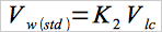 Eq. 5H-1
where:
| K2 | = | 0.001333 m3/ml for metric units |
| = | 0.04707 ft3/ml for English units. |
12.5 Moisture Content.
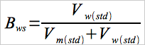 Eq. 5H-2
12.6 Solvent Wash Blank.
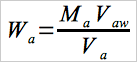 Eq. 5H-3
12.7 Total Particulate Weight.
Determine the total particulate catch from the sum of the weights obtained from containers 1, 2, 3, and 4 less the appropriate solvent blanks (see Figure 5H-4).
NOTE: Refer to Method 5, Section 8.5 to assist in calculation of results involving two filter assemblies.
12.8 Particulate Concentration.
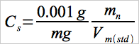 Eq. 5H-4
12.9 Sample flow Rate Adjustment.
 Eq. 5H-5
12.10 Carbon Balance for Total Moles of Exhaust Gas (dry)/kg of Wood Burned in the Exhaust Gas.
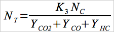 Eq. 5H-6
where:
| K3 | = | 1000 g/kg for metric units. |
| = | 1.0 lb/lb for English units. |
NOTE: The NOx/SOx portion of the gas is assumed to be negligible.
12.11 Total Stack Gas flow Rate.
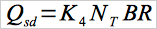 Eq. 5H-7
where:
| K4 | = | 0.02406 dscm/g-mole for metric units. |
| = | 384.8 dscf/lb-mole for English units. |
12.12 Particulate Emission Rate.
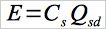 Eq. 5H-8
12.13 Proportional Rate Variation.
Calculate PR for each 10-minute interval, i, of the test run.
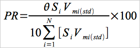 Eq. 5H-9
12.14 Acceptable Results.
If no more than 15 percent of the PR values for all the intervals fall outside the range 90 percent ≤ PR ≤ 110 percent, and if no PR value for any interval falls outside the range 75 ≤ PR ≤ 125 percent, the results are acceptable. If the PR values for the test runs are judged to be unacceptable, report the test run emission results, but do not include the test run results in calculating the weighted average emission rate, and repeat the test.
13.0 Method Performance. [Reserved]
14.0 Pollution Prevention. [Reserved]
15.0 Waste Management. [Reserved]
16.0 References.
Same as Method 5G, Section 17.0.
17.0 Tables, Diagrams, flowcharts, and Validation Data.
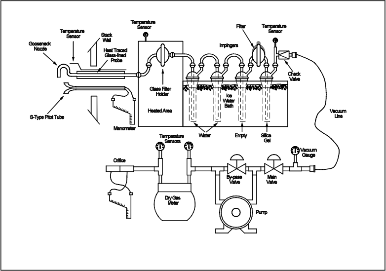
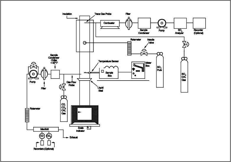
Figure 5H-2. Test System Schematic.
Data Table Printouts
- Analytical
- Ion Chromatography
- Gas Chromatography
- Gravimetrics
- Ash Resistivity
- Inks/Coatings
- Scrubber Stoichiometry
- Titrations
- Mercury Sorbent Trap
- Engineering
- Express Products
- Rental Instruments
- MET80 Mercury Monitor
- Continuous Emission Monitors
- Gas Sampling Equipment
- Mobile Power Supply
Our Resources
- Technical Resources