- Home
- Careers
- Contact
- About
-
Who we are and what we do. -
Press releases, announcements, and notable corporate information. -
We are looking for a few A people. -
We have over 40 years of innovation to create value for our customers. -
We aim to be the highest value provider of every product and service we offer. -
An easy guide to Probe fundamentals.
-
- Services
-
In additional to the analytical results we normally include an expert analysts summary.
We use our decades of experience to help you better understand your data. -
CleanAir can insures that the project goals and testing are objectives are met.
-
We can ship what you need today. It will work. You get a company of experts when you rent from CleanAir. - Thermal Performance
-
- Rental
-
Our factory reconditioning experts work to make old as good as new. -
CleanAir can provide the services required to care of your emissions measurement or power measurement instruments, no matter the age, model or manufacturer.
-
We deliver rental, emergency, or supplemental instruments and onsite services quickly, with minimal operational interruptions .
-
- Products
Featured Product

UL Listed Mobile Temporary Power
Look professional. Don't risk a OSHA fine, or worse causing your customer to get an OSHA or MSHA fine by using an unsafe mobile power distribution system. The CleanAir Temporary Power cart is UL listed! Read more... -
Reference
-
Overviews of products and services -
Learn about our companies and business -
Detailed technical information about the functioning of our products -
Guides and instructions on proper installation and service -
Guides and instructions on proper installation and service -
Drawings, configuration, materials, and limits useful for the planning and layout.
-
CleanAir's reference of video content -
Publications addressing an issue or topic
-
- Site Map
 Express
 FTIR
FTIR Mercury
 Emission Sampling Equipment
 Instrument Rental
EPA Methods List with Links
US EPA Method 5G - Determination Of Particulate Matter Emissions From Wood Heaters (Dilution Tunnel Sampling Location)
NOTE: This method does not include all of the specifications (e.g., equipment and supplies) and procedures (e.g., sampling and analytical) essential to its performance. Some material is incorporated by reference from other methods in this part. Therefore, to obtain reliable results, persons using this method should have a thorough knowledge of at least the following additional test methods: Method 1, Method 2, Method 3, Method 4, Method 5, Method 5H, and Method 28.
Necessary equipment for performing Method 5
1.0 Scope and Application.
1.1 Analyte.
Particulate matter (PM). No CAS number assigned.
1.2 Applicability.
This method is applicable for the determination of PM emissions from wood heaters.
1.3 Data Quality Objectives.
Adherence to the requirements of this method will enhance the quality of the data obtained from air pollutant sampling methods.
2.0 Summary of Method.
2.1 The exhaust from a wood heater is collected with a total collection hood, and is combined with ambient dilution air. Particulate matter is withdrawn proportionally from a single point in a sampling tunnel, and is collected on two glass fiber filters in series. The filters are maintained at a temperature of no greater than 32 C (90 F). The particulate mass is determined gravimetrically after the removal of uncombined water.
2.2 There are three sampling train approaches described in this method: (1) One dual-filter dry sampling train operated at about 0.015 m3/min (0.5 cfm), (2) One dual-filter plus impingers sampling train operated at about 0.015 m3/min (0.5 cfm), and (3) two dual-filter dry sampling trains operated simultaneously at any flow rate. Options (2) and (3) are referenced in Section 16.0 of this method. The dual-filter dry sampling train equipment and operation, option (1), are described in detail in this method.
3.0 Definitions. [Reserved]
4.0 Interferences. [Reserved]
5.0 Safety.
5.1 Disclaimer.
This method may involve hazardous materials, operations, and equipment. This test method may not address all of the safety problems associated with its use. It is the responsibility of the user of this test method to establish appropriate safety and health practices and to determine the applicability of regulatory limitations prior to performing this test method.
6.0 Equipment and Supplies.
6.1 Sample Collection.
The following items are required for sample collection:
6.1.1 Sampling train.
The sampling train configuration is shown in Figure 5G-1 and consists of the following components:
6.1.1.1 Probe.
Stainless steel (e.g., 316 or grade more corrosion resistant) or glass about 9.5 mm (3/8 in.) I.D., 0.6 m (24 in.) in length. If made of stainless steel, the Probe shall be constructed from seamless tubing.
6.1.1.2 pitot Tube.
Type S, as described in Section 6.1 of Method 2. The Type S pitot tube assembly shall have a known coefficient, determined as outlined in Method 2, Section 10. Alternatively, a Standard Pitot may be used as described in Method 2, Section 6.1.2.
6.1.1.3 Differential Pressure Gauge.
Inclined manometer or equivalent device, as described in Method 2, Section 6.2. One manometer shall be used for velocity head (Δp) readings and another (optional) for orifice differential pressure readings (ΔH).
6.1.1.4 filter Holders.
Two each made of borosilicate glass, stainless steel, or Teflon, with a glass frit or stainless steel filter support and a silicone rubber, Teflon, or Viton gasket. The holder design shall provide a positive seal against leakage from the outside or around the filters. The filter holders shall be placed in series with the backup filter holder located 25 to 100 mm (1 to 4 in.) downstream from the primary filter holder. The filter holder shall be capable of holding a filter with a 100 mm (4 in.) diameter, except as noted in Section 16.
6.1.1.5 filter temperature Monitoring System.
A Temperature Sensor capable of measuring temperature to within ± 3 C (± 5 F). The sensor shall be installed at the exit side of the front filter holder so that the sensing tip of the Temperature Sensor is in direct contact with the sample gas or in a thermowell as shown in Figure 5G-1. The Temperature Sensor shall comply with the calibration specifications in Method 2, Section 10.3. Alternatively, the sensing tip of the Temperature Sensor may be installed at the inlet side of the front filter holder.
6.1.1.6 Dryer.
Any system capable of removing water from the sample gas to less than 1.5 percent moisture (volume percent) prior to the metering system. The system shall include a Temperature Sensor for demonstrating that sample gas temperature exiting the dryer is less than 20 C (68 F).
6.1.1.7 metering System.
Same as Method 5, Section 6.1.1.9.
6.1.2 barometer.
Same as Method 5, Section 6.1.2.
6.1.3 Dilution Tunnel Gas temperature Measurement.
A Temperature Sensor capable of measuring temperature to within ± 3 C (± 5 F).
6.1.4 Dilution Tunnel.
The dilution tunnel apparatus is shown in Figure 5G-2 and consists of the following components:
6.1.4.1 Hood.
Constructed of steel with a minimum diameter of 0.3 m (1 ft) on the large end and a standard 0.15 to 0.3 m (0.5 to 1 ft) coupling capable of connecting to standard 0.15 to 0.3 m (0.5 to 1 ft) stove pipe on the small end.
6.1.4.2 90 Elbows.
Steel 90 elbows, 0.15 to 0.3 m (0.5 to 1 ft) in diameter for connecting mixing duct, straight duct and optional damper assembly. There shall be at least two 90 elbows upstream of the sampling section (see Figure 5G-2).
6.1.4.3 Straight Duct.
Steel, 0.15 to 0.3 m (0.5 to 1 ft) in diameter to provide the ducting for the dilution apparatus upstream of the sampling section. Steel duct, 0.15 m (0.5 ft) in diameter shall be used for the sampling section. In the sampling section, at least 1.2 m (4 ft) downstream of the elbow, shall be two holes (velocity traverse ports) at 90 to each other of sufficient size to allow entry of the pitot for traverse measurements. At least 1.2 m (4 ft) downstream of the velocity traverse ports, shall be one hole (sampling port) of sufficient size to allow entry of the sampling Probe. Ducts of larger diameter may be used for the sampling section, provided the specifications for minimum gas velocity and the dilution rate range shown in Section 8 are maintained. The length of duct from the hood inlet to the sampling ports shall not exceed 9.1 m (30 ft).
6.1.4.4 Mixing Baffles.
Steel semicircles (two) attached at 90 to the duct axis on opposite sides of the duct midway between the two elbows upstream of sampling section. The space between the baffles shall be about 0.3 m (1 ft).
6.1.4.5 Blower.
Squirrel cage or other fan capable of extracting gas from the dilution tunnel of sufficient flow to maintain the velocity and dilution rate specifications in Section 8 and exhausting the gas to the atmosphere.
6.2 sample recovery.
The following items are required for sample recovery: Probe brushes, wash bottles, sample storage containers, petri dishes, and funnel. Same as Method 5, Sections 6.2.1 through 6.2.4, and 6.2.8, respectively.
6.3 Sample Analysis.
The following items are required for sample analysis: glass weighing dishes, desiccator, analytical balance, beakers (250-ml or smaller), hygrometer, and Temperature Sensor.
Same as Method 5, Sections 6.3.1 through 6.3.3 and 6.3.5 through 6.3.7, respectively.
7.0 Reagents and Standards.
7.1 Sample Collection.
The following reagents are required for sample collection:
7.1.1 filters.
glass fiber filters with a minimum diameter of 100 mm (4 in.), without organic binder, exhibiting at least 99.95 percent efficiency (<0.05 percent penetration) on 0.3-micron dioctyl phthalate smoke particles. Gelman A/E 61631 has been found acceptable for this purpose.
7.1.2 Stopcock Grease.
Same as Method 5, Section 7.1.5.
7.2 sample recovery.
Acetone-reagent grade, same as Method 5, Section 7.2.
7.3 Sample Analysis.
Two reagents are required for the sample analysis:
7.3.1 Acetone.
Same as in Section 7.2.
7.3.2 Desiccant.
Anhydrous calcium sulfate, calcium chloride, or silica gel, indicating type.
8.0 Sample Collection, Preservation, Transport, and Storage.
8.1 Dilution Tunnel Assembly and Cleaning.
A schematic of a dilution tunnel is shown in Figure 5G-2. The dilution tunnel dimensions and other features are described in Section 6.1.4. Assemble the dilution tunnel, sealing joints and seams to prevent air leakage. Clean the dilution tunnel with an appropriately sized wire chimney brush before each certification test.
8.2 Draft Determination.
Prepare the wood heater as in Method 28, Section 6.2.1. Locate the dilution tunnel hood centrally over the wood heater stack exhaust. Operate the dilution tunnel blower at the flow rate to be used during the test run. Measure the draft imposed on the wood heater by the dilution tunnel (i.e., the difference in draft measured with and without the dilution tunnel operating) as described in Method 28, Section 6.2.3. Adjust the distance between the top of the wood heater stack exhaust and the dilution tunnel hood so that the dilution tunnel induced draft is less than 1.25 Pa (0.005 in. H2O). Have no fire in the wood heater, close the wood heater doors, and open fully the air supply controls during this check and adjustment.
8.3 Pretest Ignition.
Same as Method 28, Section 8.7.
8.4 Smoke Capture.
During the pretest ignition period, operate the dilution tunnel and visually monitor the wood heater stack exhaust. Operate the wood heater with the doors closed and determine that 100 percent of the exhaust gas is collected by the dilution tunnel hood. If less than 100 percent of the wood heater exhaust gas is collected, adjust the distance between the wood heater stack and the dilution tunnel hood until no visible exhaust gas is escaping. Stop the pretest ignition period, and repeat the draft determination procedure described in Section 8.2.
8.5 Velocity Measurements.
During the pretest ignition period, conduct a velocity traverse to identify the point of average velocity. This single point shall be used for measuring velocity during the test run.
8.5.1 Velocity Traverse.
Measure the diameter of the duct at the velocity traverse port location through both ports. Calculate the duct area using the average of the two diameters. A pretest leak-check of pitot lines as in Method 2, Section 8.1, is recommended. Place the calibrated pitot tube at the centroid of the stack in either of the velocity traverse ports. Adjust the damper or similar device on the blower inlet until the velocity indicated by the pitot is approximately 220 m/min (720 ft/min). Continue to read the Δp and temperature until the velocity has remained constant (less than 5 percent change) for 1 minute. Once a constant velocity is obtained at the centroid of the duct, perform a velocity traverse as outlined in Method 2, Section 8.3 using four points per traverse as outlined in Method 1. Measure the Δp and tunnel temperature at each traverse point and record the readings. Calculate the total gas flow rate using calculations contained in Method 2, Section 12. Verify that the flow rate is 4 ± 0.40 dscm/min (140 ± 14 dscf/min); if not, readjust the damper, and repeat the velocity traverse. The moisture may be assumed to be 4 percent (100 percent relative humidity at 85 F). Direct moisture measurements (e.g., according to Method 4) are also permissible.
NOTE: If burn rates exceed 3 kg/hr (6.6 lb/hr), dilution tunnel duct flow rates greater than 4 dscm/min (140 dscfm) and sampling section duct diameters larger than 150 mm (6 in.) are allowed. If larger ducts or flow rates are used, the sampling section velocity shall be at least 220 m/min (720 fpm). In order to ensure measurable particulate mass catch, it is recommended that the ratio of the average mass flow rate in the dilution tunnel to the average fuel burn rate be less than 150:1 if larger duct sizes or flow rates are used.
8.5.2 Testing Velocity Measurements.
After obtaining velocity traverse results that meet the flow rate requirements, choose a point of average velocity and place the pitot and Temperature Sensor at that location in the duct. Alternatively, locate the pitot and the Temperature Sensor at the duct centroid and calculate a velocity correction factor for the centroidal position. Mount the pitot to ensure no movement during the test run and seal the port holes to prevent any air leakage. Align the pitot opening to be parallel with the duct axis at the measurement point. Check that this condition is maintained during the test run (about 30-minute intervals). Monitor the temperature and velocity during the pretest ignition period to ensure that the proper flow rate is maintained. Make adjustments to the dilution tunnel flow rate as necessary.
8.6 Pretest Preparation.
Same as Method 5, Section 8.1.
8.7 Preparation of Sampling train.
During preparation and assembly of the sampling train, keep all openings where contamination can occur covered until just prior to assembly or until sampling is about to begin. Using a tweezer or clean disposable surgical gloves, place one labeled (identified) and weighed filter in each of the filter holders. Be sure that each filter is properly centered and that the gasket is properly placed so as to prevent the sample gas stream from circumventing the filter. Check each filter for tears after assembly is completed. Mark the Probe with heat resistant tape or by some other method to denote the proper distance into the stack or duct. Set up the train as shown in Figure 5G-1.
8.8 Leak-Check Procedures.
8.8.1 Leak-Check of metering System Shown in Figure 5G-1.
That portion of the sampling train from the pump to the orifice meter shall be leak-checked prior to initial use and after each certification or audit test. Leakage after the pump will result in less volume being recorded than is actually sampled. Use the procedure described in Method 5, Section 8.4.1. Similar leak-checks shall be conducted for other types of metering systems (i.e., without orifice meters).
8.8.2 Pretest Leak-Check.
A pretest leak-check of the sampling train is recommended, but not required. If the pretest leak check is conducted, the procedures outlined in Method 5, Section 8.4.2 should be used. A vacuum of 130 mm Hg (5 in. Hg) may be used instead of 380 mm Hg (15 in. Hg).
8.8.3 Post-Test Leak-Check.
A leak-check of the sampling train is mandatory at the conclusion of each test run. The leak-check shall be performed in accordance with the procedures outlined in Method 5, Section 8.4.2. A vacuum of 130 mm Hg (5 in. Hg) or the highest vacuum measured during the test run, whichever is greater, may be used instead of 380 mm Hg (15 in. Hg).
8.9 Preliminary Determinations.
Determine the pressure, temperature and the average velocity of the tunnel gases as in Section 8.5. Moisture content of diluted tunnel gases is assumed to be 4 percent for making flow rate calculations; the moisture content may be measured directly as in Method 4.
8.10 Sampling train Operation.
Position the Probe inlet at the stack centroid, and block off the openings around the Probe and porthole to prevent unrepresentative dilution of the gas stream. Be careful not to bump the Probe into the stack wall when removing or inserting the Probe through the porthole; this minimizes the chance of extracting deposited material.
8.10.1 Begin sampling at the start of the test run as defined in Method 28, Section 8.8.1. During the test run, maintain a sample flow rate proportional to the dilution tunnel flow rate (within 10 percent of the initial proportionality ratio) and a filter holder temperature of no greater than 32 C (90 F). The initial sample flow rate shall be approximately 0.015 m3/min (0.5 cfm).
8.10.2 For each test run, record the data required on a data sheet such as the one shown in Figure 5G-3. Be sure to record the initial console meter reading. Record the console meter readings at the beginning and end of each sampling time increment and when sampling is halted. Take other readings as indicated on Figure 5G-3 at least once each 10 minutes during the test run. Since the manometer level and zero may drift because of vibrations and temperature changes, make periodic checks during the test run.
8.10.3 For the purposes of proportional sampling rate determinations, data from calibrated flow rate devices, such as glass rotameters, may be used in lieu of incremental console meter readings. Proportional rate calculation procedures must be revised, but acceptability limits remain the same.
8.10.4 During the test run, make periodic adjustments to keep the temperature between (or upstream of) the filters at the proper level. Do not change sampling trains during the test run.
8.10.5 At the end of the test run (see Method 28, Section 6.4.6), turn off the coarse adjust valve, remove the Probe from the stack, turn off the pump, record the final console meter reading, and conduct a post-test leak-check, as outlined in Section 8.8.2. Also, leak-check the pitot lines as described in Method 2, Section 8.1; the lines must pass this leak-check in order to validate the velocity head data.
8.11 Calculation of Proportional Sampling Rate.
Calculate percent proportionality (see Section 12.7) to determine whether the run was valid or another test run should be made.
8.12 sample recovery.
Same as Method 5, Section 8.7, with the exception of the following:
8.12.1 An acetone blank volume of about 50-ml or more may be used.
8.12.2 Treat the samples as follows:
8.12.2.1 Container Nos. 1 and 1A.
Treat the two filters according to the procedures outlined in Method 5, Section 8.7.6.1. The filters may be stored either in a single container or in separate containers. Use the sum of the filter tare weights to determine the sample mass collected.
8.12.2.3 Container No. 2.
8.12.2.3.1 Taking care to see that dust on the outside of the Probe or other exterior surfaces does not get into the sample, quantitatively recover particulate matter or any condensate from the Probe and filter holders by washing and brushing these components with acetone and placing the wash in a labeled glass container. At least three cycles of brushing and rinsing are required.
8.12.2.3.2 Between sampling runs, keep brushes clean and protected from contamination.
8.12.2.3.3 After all acetone washings and particulate matter have been collected in the sample containers, tighten the lids on the sample containers so that the acetone will not leak out when transferred to the laboratory weighing area. Mark the height of the fluid levels to determine whether leakage occurs during transport. Label the containers clearly to identify contents.
8.13 Sample Transport.
Whenever possible, containers should be shipped in such a way that they remain upright at all times.
NOTE: Requirements for capping and transport of sample containers are not applicable if sample recovery and analysis occur in the same room.
9.0 Quality Control.
9.1 Miscellaneous Quality Control Measures.
| Section | Quality Control Measure | Effect |
| 8.8, 10.1-10.4 | Sampling equipment leak check and calibration | Ensures accurate measurement of stack gas flow rate, sample volume |
| 10.5 | Analytical balance calibration | Ensure accurate and precise measurement of collected particulate |
| 16.2.5 | Simultaneous, dual- train sample collection | Ensure precision of measured particulate concentration |
9.2 Volume metering System Checks.
Same as Method 5, Section 9.2.
10.0 Calibration and Standardization.
NOTE: Maintain a laboratory record of all calibrations.
10.1 pitot Tube.
The Type S pitot tube assembly shall be calibrated according to the procedure outlined in Method 2, Section 10.1, prior to the first certification test and checked semiannually, thereafter. A Standard Pitot need not be calibrated but shall be inspected and cleaned, if necessary, prior to each certification test.
10.2 Volume metering System.
10.2.1 Initial and Periodic calibration.
Before its initial use and at least semiannually thereafter, calibrate the volume metering system as described in Method 5, Section 10.3.1, except that the wet test meter with a capacity of 3.0 liters/rev (0.1 ft3/rev) may be used. Other liquid displacement systems accurate to within ±1 percent, may be used as calibration standards.
NOTE: Procedures and equipment specified in Method 5, Section 16.0, for alternative calibration standards, including calibrated console meters and critical orifices, are allowed for calibrating the console meter in the sampling train. A console meter used as a calibration standard shall be recalibrated at least once annually.
10.2.2 calibration After Use.
After each certification or audit test (four or more test runs conducted on a wood heater at the four burn rates specified in Method 28), check calibration of the metering system by performing three calibration runs at a single, intermediate flow rate as described in Method 5, Section 10.3.2. NOTE: Procedures and equipment specified in Method 5, Section 16.0, for alternative calibration standards are allowed for the post-test console meter calibration check.
10.2.3 Acceptable Variation in calibration.
If the console meter coefficient values obtained before and after a certification test differ by more than 5 percent, the certification test shall either be voided and repeated, or calculations for the certification test shall be performed using whichever meter coefficient value (i.e., before or after) gives the lower value of total sample volume.
10.3 Temperature Sensors.
Use the procedure in Method 2, Section 10.3, to calibrate Temperature Sensors before the first certification or audit test and at least semiannually, thereafter.
10.4 barometer.
Calibrate against a mercury barometer before the first certification test and at least semiannually, thereafter. If a mercury barometer is used, no calibration is necessary. Follow the manufacturer's instructions for operation.
10.5 Analytical Balance.
Perform a multipoint calibration (at least five points spanning the operational range) of the analytical balance before the first certification test and semiannually, thereafter. Before each certification test, audit the balance by weighing at least one calibration weight (class F) that corresponds to 50 to 150 percent of the weight of one filter. If the scale cannot reproduce the value of the calibration weight to within 0.1 mg, conduct the multipoint calibration before use.
11.0 Analytical Procedure.
11.1 Record the data required on a sheet such as the one shown in Figure 5G-4. Use the same analytical balance for determining tare weights and final sample weights.
11.2 Handle each sample container as follows:
11.2.1 Container Nos. 1 and 1A.
Treat the two filters according to the procedures outlined in Method 5, Section 11.2.1.
11.2.2 Container No. 2.
Same as Method 5, Section 11.2.2, except that the beaker may be smaller than 250 ml.
11.2.3 Acetone Blank Container.
Same as Method 5, Section 11.2.4, except that the beaker may be smaller than 250 ml.
12.0 Data Analysis and Calculations.
Carry out calculations, retaining at least one extra significant figure beyond that of the acquired data. Round off figures after the final calculation. Other forms of the equations may be used as long as they give equivalent results.
12.1 Nomenclature.
| Bws | = | Water vapor in the gas stream, proportion by volume (assumed to be 0.04). |
| cs | = | Concentration of particulate matter in stack gas, dry basis, corrected to standard conditions, g/dscm (gr/dscf). |
| E | = | Particulate emission rate, g/hr (lb/hr). |
| Eadj | = | Adjusted particulate emission rate, g/hr (lb/hr). |
| La | = | Maximum acceptable leakage rate for either a pretest or post-test leak-check, equal to 0.00057 m3/min (0.020 cfm) or 4 percent of the average sampling rate, whichever is less. |
| Lp | = | Leakage rate observed during the post-test leak-check, m3/min (cfm). |
| ma | = | Mass of residue of acetone blank after evaporation, mg. |
| maw | = | Mass of residue from acetone wash after evaporation, mg. |
| mn | = | Total amount of particulate matter collected, mg. |
| Mw | = | Molecular weight of water, 18.0 g/g-mole (18.0 lb/lb-mole). |
| Pbar | = | Barometric pressure at the sampling site, mm Hg (in. Hg). |
| PR | = | Percent of proportional sampling rate. |
| Ps | = | Absolute gas pressure in dilution tunnel, mm Hg (in. Hg). |
| Pstd | = | Standard absolute pressure, 760 mm Hg (29.92 in. Hg). |
| Qsd | = | Average gas flow rate in dilution tunnel, calculated as in Method 2, Equation 2-8, dscm/hr (dscf/hr). |
| Tm | = | Absolute average console meter temperature (see Figure 5G-3), K (R). |
| Tmi | = | Absolute average console meter temperature during each 10-minute interval, i, of the test run, K (R). |
| Ts | = | Absolute average gas temperature in the dilution tunnel (see Figure 5G-3), K (R). |
| Tsi | = | Absolute average gas temperature in the dilution tunnel during each 10 minute interval, i, of the test run, K (R). |
| Tstd | = | Standard absolute temperature, 293 K (R). |
| Va | = | Volume of acetone blank, ml. |
| Vaw | = | Volume of acetone used in wash, ml. |
| Vm | = | Volume of gas sample as measured by console meter, dcm (dcf). |
| Vmi | = | Volume of gas sample as measured by console meter during each 10-minute interval, i, of the test run, dcm. |
| Vm(std) | = | Volume of gas sample measured by the console meter, corrected to standard conditions, dscm (dscf). |
| Vs | = | Average gas velocity in the dilution tunnel, calculated by Method 2, Equation 2-7, m/sec (ft/sec). The dilution tunnel dry gas molecular weight may be assumed to be 29 g/g mole (lb/lb mole). |
| Vsi | = | Average gas velocity in dilution tunnel during each 10-minute interval, i, of the test run, calculated by Method 2, Equation 2-7, m/sec (ft/sec). |
| Y | = | console meter calibration factor. |
| ΔH | = | Average pressure differential across the orifice meter, if used (see Figure 5G-2), mm H2O (in. H2O). |
| U | = | Total sampling time, min. |
| 10 | = | 10 minutes, length of first sampling period. |
| 13.6 | = | Specific gravity of mercury. |
| 100 | = | Conversion to percent. |
12.2 Dry Gas Volume.
Same as Method 5, Section 12.2, except that component changes are not allowable.
12.3 Solvent Wash Blank.
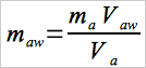 Eq. 5G-1
12.4 Total Particulate Weight.
Determine the total particulate catch, mn, from the sum of the weights obtained from Container Nos. 1, 1A, and 2, less the acetone blank (see Figure 5G-4).
12.5 Particulate Concentration.
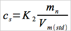 Eq. 5G-2
where:
| K2 | = | 0.001 g/mg for metric units. |
| = | 0.0154 gr/mg for English units. |
12.6 Particulate Emission Rate.
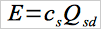 Eq. 5G-3
NOTE: Particulate emission rate results produced using the sampling train described in Section 6 and shown in Figure 5G-1 shall be adjusted for reporting purposes by the following method adjustment factor:
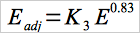 Eq. 5G-4
where:
| K3 | = | constant, 1.82 for metric units. |
| = | constant, 0.643 for English units. |
12.7 Proportional Rate Variation.
Calculate PR for each 10-minute interval, i, of the test run.
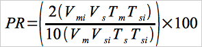 Eq. 5G-5
Alternate calculation procedures for proportional rate variation may be used if other sample flow rate data (e.g., orifice flow meters or rotameters) are monitored to maintain proportional sampling rates. The proportional rate variations shall be calculated for each 10-minute interval by comparing the stack to probe nozzle velocity ratio for each 10-minute interval to the average stack to probe nozzle velocity ratio for the test run. Proportional rate variation may be calculated for intervals shorter than 10 minutes with appropriate revisions to Equation 5G-5. If no more than 10 percent of the PR values for all the intervals exceed 90 percent ≤ PR ≤ 110 percent, and if no PR value for any interval exceeds 80 percent ≤ PR ≤ 120 percent, the results are acceptable. If the PR values for the test run are judged to be unacceptable, report the test run emission results, but do not include the results in calculating the weighted average emission rate, and repeat the test run.
13.0 Method Performance. [Reserved]
14.0 Pollution Prevention. [Reserved]
15.0 Waste Management. [Reserved]
16.0 Alternative Procedures.
16.1 Method 5H Sampling train.
The sampling train and sample collection, recovery, and analysis procedures described in Method 5H, Sections 6.1.1, 7.1, 7.2, 8.1, 8.10, 8.11, and 11.0, respectively, may be used in lieu of similar sections in Method 5G. Operation of the Method 5H sampling train in the dilution tunnel is as described in Section 8.10 of this method. filter temperatures and condenser conditions are as described in Method 5H. No adjustment to the measured particulate matter emission rate (Equation 5G-4, Section 12.6) is to be applied to the particulate emission rate measured by this alternative method.
16.2 Dual Sampling trains.
Two sampling trains may be operated simultaneously at sample flow rates other than that specified in Section 8.10, provided that the following specifications are met.
16.2.1 Sampling train.
The sampling train configuration shall be the same as specified in Section 6.1.1, except the Probe, filter, and filter holder need not be the same sizes as specified in the applicable sections. filter holders of plastic materials such as Nalgene or polycarbonate materials may be used (the Gelman 1119 filter holder has been found suitable for this purpose). With such materials, it is recommended that solvents not be used in sample recovery. The filter face velocity shall not exceed 150 mm/sec (30 ft/min) during the test run. The console meter shall be calibrated for the same flow rate range as encountered during the test runs. Two separate, complete sampling trains are required for each test run.
16.2.2 Probe Location.
Locate the two Probes in the dilution tunnel at the same level (see Section 6.1.4.3). Two sample ports are necessary. Locate the Probe inlets within the 50 mm (2 in.) diameter centroidal area of the dilution tunnel no closer than 25 mm (1 in.) apart.
16.2.3 Sampling train Operation.
Operate the sampling trains as specified in Section 8.10, maintaining proportional sampling rates and starting and stopping the two sampling trains simultaneously. The pitot values as described in Section 8.5.2 shall be used to adjust sampling rates in both sampling trains.
16.2.4 Recovery and Analysis of Sample.
Recover and analyze the samples from the two sampling trains separately, as specified in Sections 8.12 and 11.0, respectively.
16.2.4.1 For this alternative procedure, the Probe and filter holder assembly may be weighed without sample recovery (use no solvents) described above in order to determine the sample weight gains. For this approach, weigh the clean, dry Probe and filter holder assembly upstream of the front filter (without filters) to the nearest 0.1 mg to establish the tare weights. The filter holder section between the front and second filter need not be weighed. At the end of the test run, carefully clean the outside of the Probe, cap the ends, and identify the sample (label). Remove the filters from the filter holder assemblies as described for container Nos. 1 and 1A in Section 8.12.2.1. Reassemble the filter holder assembly, cap the ends, identify the sample (label), and transfer all the samples to the laboratory weighing area for final weighing. Requirements for capping and transport of sample containers are not applicable if sample recovery and analysis occur in the same room.
16.2.4.2 For this alternative procedure, filters may be weighed directly without a petri dish. If the Probe and filter holder assembly are to be weighed to determine the sample weight, rinse the Probe with acetone to remove moisture before desiccating prior to the test run. Following the test run, transport the Probe and filter holder to the desiccator, and uncap the openings of the Probe and the filter holder assembly. Desiccate for 24 hours and weigh to a constant weight. Report the results to the nearest 0.1 mg.
16.2.5 Calculations.
Calculate an emission rate (Section 12.6) for the sample from each sampling train separately and determine the average emission rate for the two values. The two emission rates shall not differ by more than 7.5 percent from the average emission rate, or 7.5 percent of the weighted average emission rate limit in the applicable subpart of the regulations, whichever is greater. If this specification is not met, the results are unacceptable. Report the results, but do not include the results in calculating the weighted average emission rate. Repeat the test run until acceptable results are achieved, report the average emission rate for the acceptable test run, and use the average in calculating the weighted average emission rate.
17.0 References.
Same as Method 5, Section 17.0, References 1 through 11, with the addition of the following:
1. Oregon Department of Environmental Quality. Standard Method for Measuring the Emissions and Efficiencies of Woodstoves. June 8, 1984. Pursuant to Oregon Administrative Rules Chapter 340, Division 21.
2. American Society for Testing and Materials. Proposed Test Methods for Heating Performance and Emissions of Residential Wood-fired Closed Combustion-Chamber Heating Appliances. E-6 Proposal P 180. August 1986.
18.0 Tables, Diagrams, flowcharts, and Validation Data.
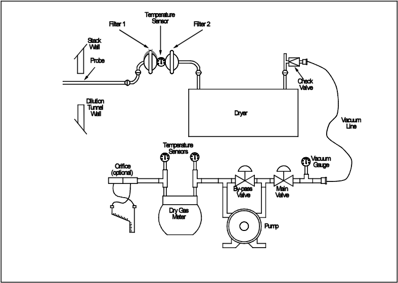
Figure 5G-1. Method 5G Sampling train.
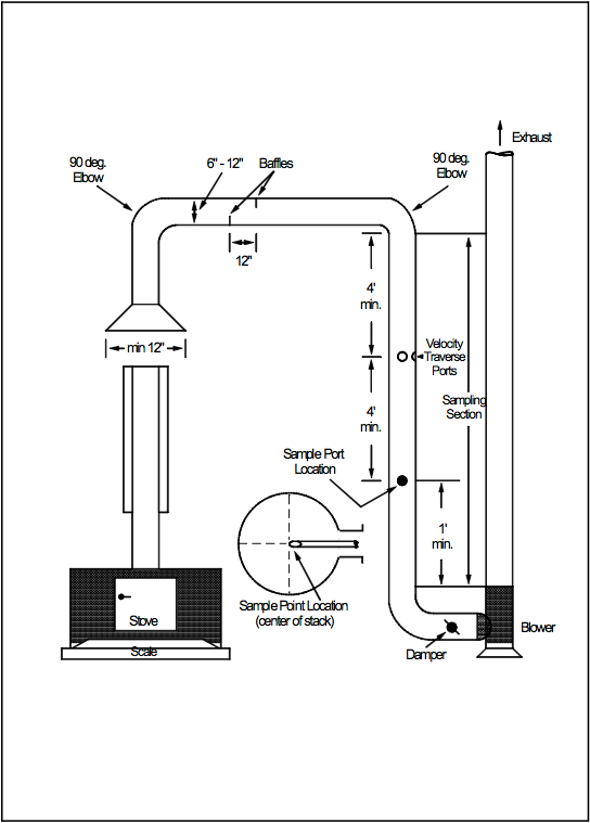
Figure 5G-2. Suggested Construction Details of the Dilution Tunnel.
Data Table Printouts
- Analytical
- Ion Chromatography
- Gas Chromatography
- Gravimetrics
- Ash Resistivity
- Inks/Coatings
- Scrubber Stoichiometry
- Titrations
- Mercury Sorbent Trap
- Engineering
- Express Products
- Rental Instruments
- MET80 Mercury Monitor
- Continuous Emission Monitors
- Gas Sampling Equipment
- Mobile Power Supply
Our Resources
- Technical Resources