- Home
- Careers
- Contact
- About
-
Who we are and what we do. -
Press releases, announcements, and notable corporate information. -
We are looking for a few A people. -
We have over 40 years of innovation to create value for our customers. -
We aim to be the highest value provider of every product and service we offer. -
An easy guide to Probe fundamentals.
-
- Services
-
In additional to the analytical results we normally include an expert analysts summary.
We use our decades of experience to help you better understand your data. -
CleanAir can insures that the project goals and testing are objectives are met.
-
We can ship what you need today. It will work. You get a company of experts when you rent from CleanAir. - Thermal Performance
-
- Rental
-
Our factory reconditioning experts work to make old as good as new. -
CleanAir can provide the services required to care of your emissions measurement or power measurement instruments, no matter the age, model or manufacturer.
-
We deliver rental, emergency, or supplemental instruments and onsite services quickly, with minimal operational interruptions .
-
- Products
Featured Product

UL Listed Mobile Temporary Power
Look professional. Don't risk a OSHA fine, or worse causing your customer to get an OSHA or MSHA fine by using an unsafe mobile power distribution system. The CleanAir Temporary Power cart is UL listed! Read more... -
Reference
-
Overviews of products and services -
Learn about our companies and business -
Detailed technical information about the functioning of our products -
Guides and instructions on proper installation and service -
Guides and instructions on proper installation and service -
Drawings, configuration, materials, and limits useful for the planning and layout.
-
CleanAir's reference of video content -
Publications addressing an issue or topic
-
- Site Map
 Express
 FTIR
FTIR Mercury
 Emission Sampling Equipment
 Instrument Rental
EPA Methods List with Links
US EPA Method 16 - Semicontinuous Determination Of Sulfur Emissions From Stationary Sources
NOTE: This method does not include all of the specifications (e.g., equipment and supplies) and procedures (e.g., sampling and analytical) essential to its performance. Some material is incorporated by reference from other methods in this part. Therefore, to obtain reliable results, persons using this method should have a thorough knowledge of at least the following additional test methods: Method 1, Method 4, Method 15, and Method 16A.
Content [ show/hide ].1.0 Scope and Application.
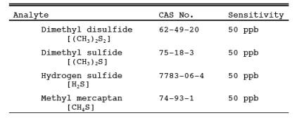
1.1 Analytes.
1.2 Applicability.
This method is applicable for the determination of total reduced sulfur (TRS) compounds from recovery furnaces, lime kilns, and smelt dissolving tanks at Kraft pulp mills and fuel gas combustion devices at petroleum refineries.
NOTE: The method described below uses the principle of gas chromatographic (GC) separation and flame photometric detection (FPD). Since there are many systems or sets of operating conditions that represent useable methods of determining sulfur emissions, all systems which employ this principle, but differ only in details of equipment and operation, may be used as alternative methods, provided that the calibration precision and sample line loss criteria are met.
1.3 Data Quality Objectives.
Adherence to the requirements of this method will enhance the quality of the data obtained from air pollutant sampling methods.
2.0 Summary of Method.
2.1 A gas sample is extracted from the emission source and an aliquot is analyzed for hydrogen sulfide (H2S), methyl mercaptan (MeSH), dimethyl sulfide (DMS), and dimethyl disulfide (DMDS) by GC/FPD. These four compounds are known collectively as TRS.
3.0 Definitions. [Reserved]
4.0 Interferences.
4.1 Moisture.
Moisture condensation in the sample delivery system, the analytical column, or the FPD burner block can cause losses or interferences. This is prevented by maintaining the Probe, filter box, and connections at a temperature of at least 120 C (248 F). Moisture is removed in the SO2 scrubber and heating the sample beyond this point is not necessary when the ambient temperature is above 0 C (32 F). Alternatively, moisture may be eliminated by heating the sample line, and by conditioning the sample with dry dilution air to lower its dew point below the operating temperature of the GC/FPD analytical system prior to analysis.
4.2 Carbon Monoxide (CO) and Carbon Dioxide (CO2).
CO and CO2 have a substantial desensitizing effect on the flame photometric detector even after dilution. Acceptable systems must demonstrate that they have eliminated this interference by some procedure such as eluting these compounds before any of the compounds to be measured. Compliance with this requirement can be demonstrated by submitting chromatograms of calibration gases with and without CO2 in the diluent gas. The CO2 level should be approximately 10 percent for the case with CO2 present. The two chromatograms should show agreement within the precision limits of Section 10.2.
4.3 Particulate Matter.
Particulate matter in gas samples can cause interference by eventual clogging of the analytical system. This interference is eliminated by using the Teflon filter after the Probe.
4.4 Sulfur Dioxide (SO2).
Sulfur dioxide is not a specific interferent but may be present in such large amounts that it cannot effectively be separated from the other compounds of interest. The SO2 scrubber described in Section 6.1.3 will effectively remove SO2 from the sample.
5.0 Safety.
5.1 Disclaimer.
This method may involve hazardous materials, operations, and equipment. This test method may not address all of the safety problems associated with its use. It is the responsibility of the user of this test method to establish appropriate safety and health practices and determine the applicability of regulatory limitations prior to performing this test method.
5.2 Hydrogen Sulfide.
A flammable, poisonous gas with the odor of rotten eggs. H2S is extremely hazardous and can cause collapse, coma, and death within a few seconds of one or two inhalations at sufficient concentrations. Low concentrations irritate the mucous membranes and may cause nausea, dizziness, and headache after exposure.
6.0 Equipment and Supplies.
6.1. Sample Collection.
The following items are needed for sample collection.
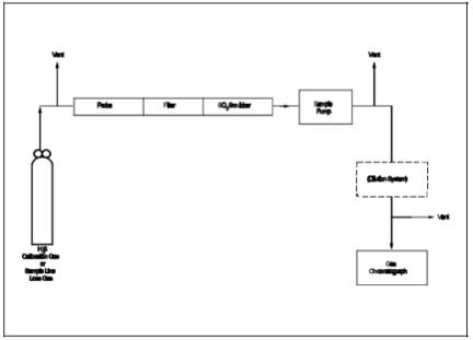
6.1.1 Probe.
Teflon or Teflon-lined stainless steel. The Probe must be heated to prevent moisture condensation. It must be designed to allow calibration gas to enter the Probe at or near the sample point entry. Any portion of the Probe that contacts the stack gas must be heated to prevent moisture condensation. Figure 16-1 illustrates the Probe used in lime kilns and other sources where significant amounts of particulate matter are present. The Probe is designed with the deflector shield placed between the sample and the gas inlet holes to reduce clogging of the filter and possible adsorption of sample gas. As an alternative, the Probe described in Section 6.1.1 of Method 16A having a probe nozzle directed away from the gas stream may be used at sources having significant amounts of particulate matter.
6.1.2 Particulate filter.
50-mm Teflon filter holder and a 1- to 2-micron porosity Teflon filter (available through Savillex Corporation, 5325 Highway 101, Minnetonka, Minnesota 55343). The filter holder must be maintained in a hot box at a temperature of at least 120 C (248 F).
6.1.3 SO2 Scrubber.
Three 300-ml Teflon segmented impingers connected in series with flexible, thick-walled, Teflon tubing. (impinger parts and tubing available through Savillex.) The first two impingers contain 100 ml of citrate buffer and the third impinger is initially dry. The tip of the tube inserted into the solution should be constricted to less than 3 mm (1/8 in.) ID and should be immersed to a depth of at least 5 cm (2 in.). Immerse the impingers in an ice water bath and maintain near 0 C (32 F). The scrubber solution will normally last for a 3-hour run before needing replacement. This will depend upon the effects of moisture and particulate matter on the solution strength and pH. Connections between the Probe, particulate filter, and SO2 scrubber must be made of Teflon and as short in length as possible. All portions of the Probe, particulate filter, and connections prior to the SO2scrubber (or alternative point of moisture removal) must be maintained at a temperature of at least 120 C (248 F).
6.1.4 Sample Line.
Teflon, no greater than 1.3 cm (1/2 in.) ID. Alternative materials, such as virgin Nylon, may be used provided the line loss test is acceptable.
6.1.5 sample pump>.
The sample pump> must be a leakless Teflon-coated diaphragm type or equivalent.
6.2 Analysis.
The following items are needed for sample analysis:
6.2.1 Dilution System.
Needed only for high sample concentrations. The dilution system must be constructed such that all sample contacts are made of Teflon, glass, or stainless steel.
6.2.2 Gas Chromatograph.
The gas chromatograph must have at least the following components:
6.2.2.1 oven.
Capable of maintaining the separation column at the proper operating temperature ± 1 C (2 F).
6.2.2.2 temperature Gauge.
To monitor column oven, detector, and exhaust temperature ± 1 C (2 F).
6.2.2.3 flow System.
Gas metering system to measure sample, fuel, combustion gas, and carrier gas flows.
6.2.2.4 Flame Photometric Detector.
6.2.2.4.1 Electrometer.
Capable of full scale amplification of linear ranges of 10-9 to 10-4 amperes full scale.
6.2.2.4.2 Power Supply.
Capable of delivering up to 750 volts.
6.2.2.4.3 Recorder.
Compatible with the output voltage range of the electrometer.
6.2.2.4.4 Rotary Gas Valves.
Multiport Teflon-lined valves equipped with sample loop. Sample loop volumes must be chosen to provide the needed analytical range. Teflon tubing and fittings must be used throughout to present an inert surface for sample gas. The gas chromatograph must be calibrated with the sample loop used for sample analysis.
6.2.3 Gas Chromatogram Columns.
The column system must be demonstrated to be capable of resolving the four major reduced sulfur compounds: H2S, MeSH, DMS, and DMDS. It must also demonstrate freedom from known interferences. To demonstrate that adequate resolution has been achieved, submit a chromatogram of a calibration gas containing all four of the TRS compounds in the concentration range of the applicable standard. Adequate resolution will be defined as base line separation of adjacent peaks when the amplifier attenuation is set so that the smaller peak is at least 50 percent of full scale. Baseline separation is defined as a return to zero ±5 percent in the interval between peaks. Systems not meeting this criteria may be considered alternate methods subject to the approval of the Administrator.
6.3 calibration.
A calibration system, containing the following components, is required (see Figure 16-2).
6.3.1 Tube Chamber.
Chamber of glass or Teflon of sufficient dimensions to house permeation tubes.
6.3.2 flow System.
To measure air flow over permeation tubes at ±2 percent. flow over the permeation device may also be determined using a soap bubble flow meter.
6.3.3 Constant temperature Bath.
Device capable of maintaining the permeation tubes at the calibration temperature within 0.1 C (0.2 F).
6.3.4 temperature Gauge.
Thermometer or equivalent to monitor bath temperature within 1 C (2 F).
7.0 Reagents and Standards.
7.1 Fuel. Hydrogen (H2), prepurified grade or better.
7.2 Combustion Gas.
Oxygen (O2) or air, research purity or better.7.3 Carrier Gas.
Prepurified grade or better.
7.4 Diluent (if required).
Air containing less than 50 ppb total sulfur compounds and less than 10 ppmv each of moisture and total hydrocarbons.
7.5 calibration Gases.
7.5.1 Permeation tubes, one each of H2S, MeSH, DMS, and DMDS, gravimetrically calibrated and certified at some convenient operating temperature. These tubes consist of hermetically sealed FEP Teflon tubing in which a liquefied gaseous substance is enclosed. The enclosed gas permeates through the tubing wall at a constant rate. When the temperature is constant, calibration gases covering a wide range of known concentrations can be generated by varying and accurately measuring the flow rate of diluent gas passing over the tubes. These calibration gases are used to calibrate the GC/FPD system and the dilution system.
7.5.2 Cylinder Gases.
Cylinder gases may be used as alternatives to permeation devices. The gases must be traceable to a primary standard (such as permeation tubes) and not used beyond the certification expiration date.
7.6 Citrate Buffer and Sample Line Loss Gas.
Same as Method 15, Sections 7.6 and 7.7.
8.0 Sample Collection, Preservation, Storage, and Transport.
Same as Method 15, Section 8.0, except that the references to the dilution system may not be applicable.
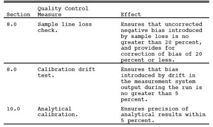
9.0 Quality Control.
10.0 Calibration and Standardization.
Same as Method 15, Section 10.0, with the following addition and exceptions:
10.1 Use the four compounds that comprise TRS instead of the three reduced sulfur compounds measured by Method 15.
10.2 flow meter.
calibration before each test run is recommended, but not required; calibration following each test series is mandatory. Calibrate each flow meter after each complete test series with a wet-test meter. If the flow measuring device differs from the wet-test meter by 5 percent or more, the completed test runs must be voided. Alternatively, the flow data that yield the lower flow measurement may be used. flow over the permeation device may also be determined using a soap bubble flow meter.
11.0 Analytical Procedure.
Sample collection and analysis are concurrent for this method (see Section 8.0).
12.0 Data Analysis and Calculations.
12.1 Concentration of Reduced Sulfur Compounds.
Calculate the average concentration of each of the four analytes (i.e., DMDS, DMS, H2S, and MeSH) over the sample run (specified in Section 8.2 of Method 15 as 16 injections).
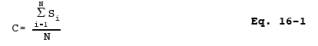
where:
Si = Concentration of any reduced sulfur compound from the ith sample injection, ppm.
C = Average concentration of any one of the reduced sulfur compounds for the entire run, ppm.
N = Number of injections in any run period.
12.2 TRS Concentration. Using Equation 16-2, calculate the TRS concentration for each sample run.

where:
CTRS = TRS concentration, ppmv.
CH2S = Hydrogen sulfide concentration, ppmv.
CMeSH = Methyl mercaptan concentration, ppmv.
CDMS = Dimethyl sulfide concentration, ppmv.
CDMDS = Dimethyl disulfide concentration, ppmv.
d = Dilution factor, dimensionless.
12.3 Average TRS Concentration. Calculate the average TRS concentration for all sample runs performed.

where:
Average TRS = Average total reduced sulfur in ppm.
TRSi = Total reduced sulfur in ppm as determined by Equation 16-2.
N = Number of samples.
Bwo = Fraction of volume of water vapor in the gas stream as determined by Method 4 -Determination of Moisture in Stack Gases.
13.0 Method Performance.
13.1 Analytical Range.
The analytical range will vary with the sample loop size. Typically, the analytical range may extend from 0.1 to 100 ppmv using 10- to 0.1-ml sample loop sizes. This eliminates the need for sample dilution in most cases.
13.2 Sensitivity.
Using the 10-ml sample size, the minimum detectable concentration is approximately 50 ppb.
14.0 Pollution Prevention. [Reserved]
15.0 Waste Management. [Reserved]
16.0 References.
1. O'Keeffe, A.E., and G.C. Ortman. "Primary Standards for Trace Gas Analysis." Analytical Chemical Journal, 38,76. 1966.
2. Stevens, R.K., A.E. O'Keeffe, and G.C. Ortman. "Absolute calibration of a Flame Photometric Detector to Volatile Sulfur Compounds at Sub-Part-Per-Million Levels." Environmental Science and Technology, 3:7. July 1969.
3. Mulik, J.D., R.K. Stevens, and R. Baumgardner. "An Analytical System Designed to Measure Multiple Malodorous Compounds Related to Kraft Mill Activities." Presented at the 12th Conference on Methods in Air Pollution and Industrial Hygiene Studies, University of Southern California, Los Angeles, CA. April 6-8, 1971.
4. Devonald, R.H., R.S. Serenius, and A.D. McIntyre. "Evaluation of the Flame Photometric Detector for Analysis of Sulfur Compounds." Pulp and Paper Magazine of Canada, 73,3. March 1972.
5. Grimley, K.W., W.S. Smith, and R.M. Martin. "The Use of a Dynamic Dilution System in the Conditioning of Stack Gases for Automated Analysis by a Mobile Sampling Van." Presented at the 63rd Annual APCA Meeting, St. Louis, MO. June 14-19, 1970.
6. General Reference. Standard Methods of Chemical Analysis, Volumes III-A and III-B Instrumental Methods. Sixth Edition. Van Nostrand Reinhold Co.
17.0 Tables, Diagrams, flowcharts, and Validation Data.
Figure 16-1. Probe used for Sample Gas Containing High Particulate Matter Loading.
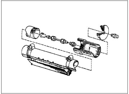
Figure 16-2. calibration System.