- Home
- Careers
- Contact
- About
-
Who we are and what we do. -
Press releases, announcements, and notable corporate information. -
We are looking for a few A people. -
We have over 40 years of innovation to create value for our customers. -
We aim to be the highest value provider of every product and service we offer. -
An easy guide to Probe fundamentals.
-
- Services
-
In additional to the analytical results we normally include an expert analysts summary.
We use our decades of experience to help you better understand your data. -
CleanAir can insures that the project goals and testing are objectives are met.
-
We can ship what you need today. It will work. You get a company of experts when you rent from CleanAir. - Thermal Performance
-
- Rental
-
Our factory reconditioning experts work to make old as good as new. -
CleanAir can provide the services required to care of your emissions measurement or power measurement instruments, no matter the age, model or manufacturer.
-
We deliver rental, emergency, or supplemental instruments and onsite services quickly, with minimal operational interruptions .
-
- Products
Featured Product

UL Listed Mobile Temporary Power
Look professional. Don't risk a OSHA fine, or worse causing your customer to get an OSHA or MSHA fine by using an unsafe mobile power distribution system. The CleanAir Temporary Power cart is UL listed! Read more... -
Reference
-
Overviews of products and services -
Learn about our companies and business -
Detailed technical information about the functioning of our products -
Guides and instructions on proper installation and service -
Guides and instructions on proper installation and service -
Drawings, configuration, materials, and limits useful for the planning and layout.
-
CleanAir's reference of video content -
Publications addressing an issue or topic
-
- Site Map
 Express
 FTIR
FTIR Mercury
 Emission Sampling Equipment
 Instrument Rental
EPA Methods List with Links
METHOD 6 - DETERMINATION OF SULFUR DIOXIDE EMISSIONS FROM STATIONARY SOURCES
NOTE: This method does not include all of the specifications (e.g., equipment and supplies) and procedures (e.g., sampling and analytical) essential to its performance. Some material is incorporated by reference from other methods in this part. Therefore, to obtain reliable results, persons using this method should have a thorough knowledge of at least the following additional test methods: Method 1, Method 2, Method 3, Method 5, and Method 8.
Content [ show/hide ].1.0 Scope and Application.
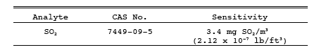
1.1 Analytes.
1.2 Applicability.
This method applies to the measurement of sulfur dioxide (SO2) emissions from stationary sources.
1.3 Data Quality Objectives.
Adherence to the requirements of this method will enhance the quality of the data obtained from air pollutant sampling methods.
2.0 Summary of Method.
2.1 A gas sample is extracted from the sampling point in the stack. The SO2 and the sulfur trioxide, including those fractions in any sulfur acid mist, are separated. The SO2fraction is measured by the barium-thorin titration method.
3.0 Definitions. [Reserved]
4.0 Interferences.
4.1 Free Ammonia.
Free ammonia interferes with this method by reacting with SO2 to form particulate sulfite and by reacting with the indicator. If free ammonia is present (this can be determined by knowledge of the process and/or noticing white particulate matter in the Probe and isopropanol bubbler), alternative methods, subject to the approval of the Administrator are required. One approved alternative is listed in Reference 13 of Section 17.0.
4.2 Water-Soluble Cations and Fluorides.
The cations and fluorides are removed by a glass wool filter and an isopropanol bubbler; therefore, they do not affect the SO2 analysis. When samples are collected from a gas stream with high concentrations of metallic fumes (i.e., very fine cation aerosols) a high-efficiency glass fiber filter must be used in place of the glass wool plug (i.e., the one in the Probe) to remove the cation interferent.
5.0 Safety.
5.1 Disclaimer.
This method may involve hazardous materials, operations, and equipment. This test method may not address all of the safety problems associated with its use. It is the responsibility of the user to establish appropriate safety and health practices and determine the applicability of regulatory limitations before performing this test method.
5.2 Corrosive reagents.
The following reagents are hazardous. Personal protective equipment and safe procedures are useful in preventing chemical splashes. If contact occurs, immediately flush with copious amounts of water for at least 15 minutes. Remove clothing under shower and decontaminate. Treat residual chemical burns as thermal burns.
5.2.1 Hydrogen Peroxide (H2O2).
Irritating to eyes, skin, nose, and lungs. 30% H2O2 is a strong oxidizing agent. Avoid contact with skin, eyes, and combustible material. Wear gloves when handling.
5.2.2 Sodium Hydroxide (NaOH).
Causes severe damage to eyes and skin. Inhalation causes irritation to nose, throat, and lungs. Reacts exothermically with limited amounts of water.
5.2.3 Sulfuric Acid (H2SO4).
Rapidly destructive to body tissue. Will cause third degree burns. Eye damage may result in blindness. Inhalation may be fatal from spasm of the larynx, usually within 30 minutes. May cause lung tissue damage with edema. 1 mg/m3 for 8 hours will cause lung damage or, in higher concentrations, death. Provide ventilation to limit inhalation. Reacts violently with metals and organics.
6.0 Equipment and Supplies.
6.1 Sample Collection.
The following items are required for sample collection:
6.1.1 Sampling train.
A schematic of the sampling train is shown in Figure 6-1. The sampling equipment described in Method 8 may be substituted in place of the midget impinger equipment of Method 6. However, the Method 8 train must be modified to include a heated filter between the Probe and isopropanol impinger, and the operation of the sampling train and sample analysis must be at the flow rates and solution volumes defined in Method 8. Alternatively, SO2 may be determined simultaneously with particulate matter and moisture determinations by either (1) replacing the water in a Method 5 impinger system with a 3 percent H2O2 solution, or (2) replacing the Method 5 water impinger system with a Method 8 isopropanol-filter-H2O2 system. The analysis for SO2 must be consistent with the procedure of Method 8. The Method 6 sampling train consists of the following components:
6.1.1.1 Probe.
Borosilicate glass or stainless steel (other materials of construction may be used, subject to the approval of the Administrator), approximately 6 mm (0.25 in.) inside diameter, with a heating system to prevent water condensation and a filter (either in-stack or heated out-of-stack) to remove particulate matter, including sulfuric acid mist. A plug of glass wool is a satisfactory filter.
6.1.1.2 Bubbler and impingers.
One midget bubbler with medium-coarse glass frit and borosilicate or quartz glass wool packed in top (see Figure 6-1) to prevent sulfuric acid mist carryover, and three 30-ml midget impingers. The midget bubbler and midget impingers must be connected in series with leak-free glass connectors. Silicone grease may be used, if necessary, to prevent leakage. A midget impinger may be used in place of the midget bubbler.
NOTE: Other collection absorbers and flow rates may be used, subject to the approval of the Administrator, but the collection efficiency must be shown to be at least 99 percent for each test run and must be documented in the report. If the efficiency is found to be acceptable after a series of three tests, further documentation is not required. To conduct the efficiency test, an extra absorber must be added and analyzed separately. This extra absorber must not contain more than 1 percent of the total SO2.
6.1.1.3 glass Wool.
Borosilicate or quartz.
6.1.1.4 Stopcock Grease.
Acetone-insoluble, heat-stable silicone grease may be used, if necessary.
6.1.1.5 tenperature sensor.
Dial thermometer, or equivalent, to measure temperature of gas leaving impinger train to within 1 C (2 F).
6.1.1.6 Drying Tube.
Tube packed with 6- to 16-mesh indicating-type silica gel, or equivalent, to dry the gas sample and to protect the meter and pump. If silica gel is previously used, dry at 177 C (350 F) for 2 hours. New silica gel may be used as received. Alternatively, other types of desiccants (equivalent or better) may be used, subject to the approval of the Administrator.
6.1.1.7 Valve.
Needle valve, to regulate sample gas flow rate.
6.1.1.8 pump.
Leak-free diaphragm pump, or equivalent, to pull gas through the train. Install a small surge tank between the pump and rate meter to negate the pulsation effect of the diaphragm pump on the rate meter.
6.1.1.9 Rate Meter.
Rotameter, or equivalent, capable of measuring flow rate to within 2 percent of the selected flow rate of about 1 liter/min (0.035 cfm).
6.1.1.10 Volume meter.
dry gas meter (DGM), sufficiently accurate to measure the sample volume to within 2 percent, calibrated at the selected flow rate and conditions actually encountered during sampling, and equipped with a tenperature sensor (dial thermometer, or equivalent) capable of measuring temperature accurately to within 3 C (5.4 F). A critical orifice may be used in place of the DGM specified in this section provided that it is selected, calibrated, and used as specified in Section 16.0.
6.1.2 barometer.
Mercury, aneroid, or other barometer capable of measuring atmospheric pressure to within 2.5 mm Hg (0.1 in. Hg). See the NOTE in Method 5, Section 6.1.2.
6.1.3 Vacuum Gauge and Rotameter.
At least 760-mm Hg (30-in. Hg) gauge and 0- to 40-ml/min rotameter, to be used for leak-check of the sampling train.
6.2 Sample Recovery.
The following items are needed for sample recovery:
6.2.1 Wash Bottles. Two polyethylene or glass bottles, 500-ml.
6.2.2 Storage Bottles. Polyethylene bottles, 100-ml, to store impinger samples (one per sample).
6.3 Sample Analysis.
The following equipment is needed for sample analysis:
6.3.1 Pipettes. Volumetric type, 5-ml, 20-ml (one needed per sample), and 25-ml sizes.
6.3.2 Volumetric Flasks. 100-ml size (one per sample) and 1000-ml size.
6.3.3 Burettes. 5- and 50-ml sizes.
6.3.4 Erlenmeyer Flasks. 250-ml size (one for each sample, blank, and standard).
6.3.5 Dropping Bottle. 125-ml size, to add indicator.
6.3.6 Graduated Cylinder. 100-ml size.
6.3.7 Spectrophotometer. To measure absorbance at 352 nm.
7.0 Reagents and Standards.
NOTE: Unless otherwise indicated, all reagents must conform to the specifications established by the Committee on Analytical Reagents of the American Chemical Society. Where such specifications are not available, use the best available grade.
7.1 Sample Collection.
The following reagents are required for sample collection:
7.1.1 Water.
Deionized distilled to conform to ASTM Specification D 1193-77 or 91 Type 3 (incorporated by reference - see 60.17). The KMnO4 test for oxidizable organic matter may be omitted when high concentrations of organic matter are not expected to be present.
7.1.2 Isopropanol, 80 Percent by Volume.
Mix 80 ml of isopropanol with 20 ml of water.
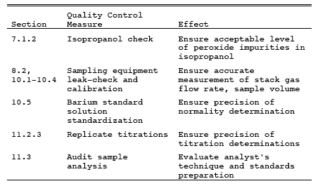
7.1.2.1 Check each lot of isopropanol for peroxide impurities as follows: Shake 10 ml of isopropanol with 10 ml of freshly prepared 10 percent potassium iodide solution. Prepare a blank by similarly treating 10 ml of water. After 1 minute, read the absorbance at 352 nm on a spectrophotometer using a 1-cm path length. If absorbance exceeds 0.1, reject alcohol for use.
7.1.2.2 Peroxides may be removed from isopropanol by redistilling or by passage through a column of activated alumina; however, reagent grade isopropanol with suitably low peroxide levels may be obtained from commercial sources. Rejection of contaminated lots may, therefore, be a more efficient procedure.
7.1.3 Hydrogen Peroxide (H2O2), 3 Percent by Volume.
Add 10 ml of 30 percent H2O2to 90 ml of water. Prepare fresh daily.
7.1.4 Potassium Iodide Solution, 10 Percent Weight by Volume (w/v).
Dissolve 10.0 g of KI in water, and dilute to 100 ml. Prepare when needed.
7.2 Sample Recovery.
The following reagents are required for sample recovery:
7.2.1 Water.
Same as in Section 7.1.1.
7.2.2 Isopropanol, 80 Percent by Volume.
Same as in Section 7.1.2.
7.3 Sample Analysis.
The following reagents and standards are required for sample analysis:
7.3.1 Water.
Same as in Section 7.1.1.
7.3.2 Isopropanol, 100 Percent.
7.3.3 Thorin Indicator.
1-(o-arsonophenylazo)-2-naphthol-3, 6-disulfonic acid, disodium salt, or equivalent. Dissolve 0.20 g in 100 ml of water.
7.3.4 Barium Standard Solution, 0.0100 N.
Dissolve 1.95 g of barium perchlorate trihydrate [Ba(ClO4)2 3H2O] in 200 ml water, and dilute to 1 liter with isopropanol. Alternatively, 1.22 g of barium chloride dihydrate [BaCl2 2H2O] may be used instead of the barium perchlorate trihydrate. Standardize as in Section 10.5.
7.3.5 Sulfuric Acid Standard, 0.0100 N.
Purchase or standardize to ± 0.0002 N against 0.0100 N NaOH which has previously been standardized against potassium acid phthalate (primary standard grade).
7.3.6 Quality Assurance Audit Samples.
When making compliance determinations, audit samples, if available must be obtained from the appropriate EPA Regional Office or from the responsible enforcement authority and analyzed in conjunction with the field samples.
Note: The responsible enforcement authority should be notified at least 30 days prior to the test date to allow sufficient time for sample delivery.
8.0 Sample Collection, Preservation, Storage and Transport.
8.1 Preparation of Sampling train.
Measure 15 ml of 80 percent isopropanol into the midget bubbler and 15 ml of 3 percent H2O2 into each of the first two midget impingers. Leave the final midget impinger dry. Assemble the train as shown in Figure 6-1. Adjust the Probe heater to a temperature sufficient to prevent water condensation. Place crushed ice and water around the impingers.
8.2 Sampling train Leak-Check Procedure.
A leak-check prior to the sampling run is recommended, but not required. A leak-check after the sampling run is mandatory. The leak-check procedure is as follows:
8.2.1 Temporarily attach a suitable (e.g., 0- to 40-ml/min) rotameter to the outlet of the DGM, and place a vacuum gauge at or near the Probe inlet. Plug the Probe inlet, pull a vacuum of at least 250 mm Hg (10 in. Hg), and note the flow rate as indicated by the rotameter. A leakage rate in excess of 2 percent of the average sampling rate is not acceptable.
NOTE: Carefully (i.e., slowly) release the Probe inlet plug before turning off the pump.
8.2.2 It is suggested (not mandatory) that the pump be leak-checked separately, either prior to or after the sampling run. To leak-check the pump, proceed as follows: Disconnect the drying tube from the Probe-impinger assembly. Place a vacuum gauge at the inlet to either the drying tube or the pump, pull a vacuum of 250 mm Hg (10 in. Hg), plug or pinch off the outlet of the flow meter, and then turn off the pump. The vacuum should remain stable for at least 30 seconds. If performed prior to the sampling run, the pump leak-check shall precede the leak-check of the sampling train described immediately above; if performed after the sampling run, the pump leak-check shall follow the sampling train leak-check.
8.2.3 Other leak-check procedures may be used, subject to the approval of the Administrator.
8.3 Sample Collection.
8.3.1 Record the initial DGM reading and barometric pressure. To begin sampling, position the tip of the Probe at the sampling point, connect the Probe to the bubbler, and start the pump. Adjust the sample flow to a constant rate of approximately 1.0 liter/min as indicated by the rate meter. Maintain this constant rate (± 10 percent) during the entire sampling run.
8.3.2 Take readings (DGM volume, temperatures at DGM and at impinger outlet, and rate meter flow rate) at least every 5 minutes. Add more ice during the run to keep the temperature of the gases leaving the last impinger at 20 C (68 F) or less.
8.3.3 At the conclusion of each run, turn off the pump, remove the Probe from the stack, and record the final readings. Conduct a leak-check as described in Section 8.2. (This leak-check is mandatory.) If a leak is detected, void the test run or use procedures acceptable to the Administrator to adjust the sample volume for the leakage.
8.3.4 Drain the ice bath, and purge the remaining part of the train by drawing clean ambient air through the system for 15 minutes at the sampling rate. Clean ambient air can be provided by passing air through a charcoal filter or through an extra midget impinger containing 15 ml of 3 percent H2O2. Alternatively, ambient air without purification may be used.
8.4 Sample Recovery.
Disconnect the impingers after purging. Discard the contents of the midget bubbler. Pour the contents of the midget impingers into a leak-free polyethylene bottle for shipment. Rinse the three midget impingers and the connecting tubes with water, and add the rinse to the same storage container. Mark the fluid level. Seal and identify the sample container.
9.0 Quality Control.
10.0 Calibration and Standardization.
10.1 Volume metering System.
10.1.1 Initial calibration.
10.1.1.1 Before its initial use in the field, leak-check the metering system (drying tube, needle valve, pump, rate meter, and DGM) as follows: Place a vacuum gauge at the inlet to the drying tube and pull a vacuum of 250 mm Hg (10 in. Hg). Plug or pinch off the outlet of the flow meter, and then turn off the pump. The vacuum must remain stable for at least 30 seconds. Carefully release the vacuum gauge before releasing the flow meter end.
10.1.1.2 Remove the drying tube, and calibrate the metering system (at the sampling flow rate specified by the method) as follows: Connect an appropriately sized wet-test meter (e.g., 1 liter per revolution) to the inlet of the needle valve. Make three independent calibration runs, using at least five revolutions of the DGM per run. Calculate the calibration factor Y (wet-test meter calibration volume divided by the DGM volume, both volumes adjusted to the same reference temperature and pressure) for each run, and average the results (Yi). If any Y-value deviates by more than 2 percent from (Yi), the metering system is unacceptable for use. If the metering system is acceptable, use (Yi) as the calibration factor for subsequent test runs.
10.1.2 Post-Test calibration Check.
After each field test series, conduct a calibration check using the procedures outlined in Section 10.1.1.2, except that three or more revolutions of the DGM may be used, and only two independent runs need be made. If the average of the two post-test calibration factors does not deviate by more than 5 percent from Yi, then Yi is accepted as the DGM calibration factor (Y), which is used in Equation 6-1 to calculate collected sample volume (see Section 12.2). If the deviation is more than 5 percent, recalibrate the metering system as in Section 10.1.1, and determine a posttest calibration factor (Yf). Compare Yi and Yf; the smaller of the two factors is accepted as the DGM calibration factor. If recalibration indicates that the metering system is unacceptable for use, either void the test run or use methods, subject to the approval of the Administrator, to determine an acceptable value for the collected sample volume.
10.1.3 DGM as a calibration Standard.
A DGM may be used as a calibration standard for volume measurements in place of the wet-test meter specified in Section 10.1.1.2, provided that it is calibrated initially and recalibrated periodically according to the same procedures outlined in Method 5, Section 10.3 with the following exceptions: (a) the DGM is calibrated against a wet-test meter having a capacity of 1 liter/rev (0.035 ft3/rev) or 3 liters/rev (0.1 ft3/rev) and having the capability of measuring volume to within 1 percent; (b) the DGM is calibrated at 1 liter/min (0.035 cfm); and (c) the meter box of the Method 6 sampling train is calibrated at the same flow rate.
10.2 tenperature sensors.
Calibrate against mercury-in-glass thermometers.
10.3 Rate Meter.
The rate meter need not be calibrated, but should be cleaned and maintained according to the manufacturer's instructions.
10.4 barometer.
Calibrate against a mercury barometer.
10.5 Barium Standard Solution.
Standardize the barium perchlorate or chloride solution against 25 ml of standard sulfuric acid to which 100 ml of 100 percent isopropanol has been added. Run duplicate analyses. Calculate the normality using the average of duplicate analyses where the titrations agree within 1 percent or 0.2 ml, whichever is larger.
11.0 Analytical Procedure.
11.1 Sample Loss Check.
Note level of liquid in container and confirm whether any sample was lost during shipment; note this finding on the analytical data sheet. If a noticeable amount of leakage has occurred, either void the sample or use methods, subject to the approval of the Administrator, to correct the final results.
11.2 Sample Analysis.
11.2.1 Transfer the contents of the storage container to a 100-ml volumetric flask, dilute to exactly 100 ml with water, and mix the diluted sample.
11.2.2 Pipette a 20-ml aliquot of the diluted sample into a 250-ml Erlenmeyer flask and add 80 ml of 100 percent isopropanol plus two to four drops of thorin indicator. While stirring the solution, titrate to a pink endpoint using 0.0100 N barium standard solution.
11.2.3 Repeat the procedures in Section 11.2.2, and average the titration volumes. Run a blank with each series of samples. Replicate titrations must agree within 1 percent or 0.2 ml, whichever is larger.
NOTE: Protect the 0.0100 N barium standard solution from evaporation at all times.
11.3 Audit Sample Analysis.
11.3.1 When the method is used to analyze samples to demonstrate compliance with a source emission regulation, an audit sample, if available, must be analyzed.
11.3.2 Concurrently analyze the audit sample and the compliance samples in the same manner to evaluate the technique of the analyst and the standards preparation.
11.3.3 The same analyst, analytical reagents, and analytical system must be used for the compliance samples and the audit sample. If this condition is met, duplicate auditing of subsequent compliance analyses for the same enforcement agency within a 30-day period is waived. An audit sample set may not be used to validate different sets of compliance samples under the jurisdiction of separate enforcement agencies, unless prior arrangements have been made with both enforcement agencies.
11.4 Audit Sample Results.
11.4.1 Calculate the audit sample concentrations and submit results using the instructions provided with the audit samples.
11.4.2 Report the results of the audit samples and the compliance determination samples along with their identification numbers, and the analyst's name to the responsible enforcement authority. Include this information with reports of any subsequent compliance analyses for the same enforcement authority during the 30-day period.
11.4.3 The concentrations of the audit samples obtained by the analyst must agree within 5 percent of the actual concentration. If the 5 percent specification is not met, reanalyze the compliance and audit samples, and include initial and reanalysis values in the test report.
11.4.4 Failure to meet the 5-percent specification may require retests until the audit problems are resolved. However, if the audit results do not affect the compliance or noncompliance status of the affected facility, the Administrator may waive the reanalysis requirement, further audits, or retests and accept the results of the compliance test. While steps are being taken to resolve audit analysis problems, the Administrator may also choose to use the data to determine the compliance or noncompliance status of the affected facility.
12.0 Data Analysis and Calculations.
Carry out calculations, retaining at least one extra significant figure beyond that of the acquired data. Round off figures after final calculation.
12.1 Nomenclature.
Ca = Actual concentration of SO2 in audit sample, mg/dscm.
Cd = Determined concentration of SO2 in audit sample, mg/dscm.
CSO2 = Concentration of SO2, dry basis, corrected to standard conditions, mg/dscm (lb/dscf).
N = Normality of barium standard titrant, meq/ml.
Pbar = Barometric pressure, mm Hg (in. Hg).
Pstd = Standard absolute pressure, 760 mm Hg (29.92 in. Hg).
RE = Relative error of QA audit sample analysis, percent
Tm = Average DGM absolute temperature, K (R).
Tstd = Standard absolute temperature, 293 K (528 R).
Va = Volume of sample aliquot titrated, ml.
Vm = Dry gas volume as measured by the DGM, dcm (dcf).
Vm(std)= Dry gas volume measured by the DGM, corrected to standard conditions, dscm (dscf).
Vsoln = Total volume of solution in which the SO>2 sample is contained, 100 ml.
Vt = Volume of barium standard titrant used for the sample (average of replicate titration), ml.
Vtb = Volume of barium standard titrant used for the blank, ml.
Y = DGM calibration factor.
12.2 Dry Sample Gas Volume, Corrected to Standard Conditions.
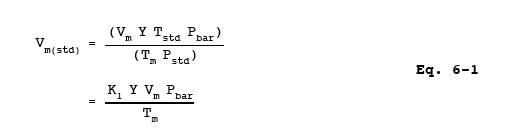
where:
K1 = 0.3855 K/mm Hg for metric units,
= 17.65 R/in. Hg for English units.
12.3 SO2 Concentration.
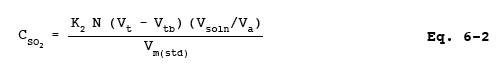
where:
K2 = 32.03 mg SO2/meq for metric units,
= 7.061 x 10⁻⁵ lb SO2/meq for English units.
12.4 Relative Error for QA Audit Samples.
![]()
13.0 Method Performance.
13.1 Range.
The minimum detectable limit of the method has been determined to be 3.4 mg SO2/m3 (2.12 x 10⁻⁷ lb/ft3). Although no upper limit has been established, tests have shown that concentrations as high as 80,000 mg/m3 (0.005 lb/ft3) of SO2 can be collected efficiently at a rate of 1.0 liter/min (0.035 cfm) for 20 minutes in two midget impingers, each containing 15 ml of 3 percent H2O2. Based on theoretical calculations, the upper concentration limit in a 20 liter (0.7 ft3) sample is about 93,300 mg/m3 (0.00583 lb/ft3).
14.0 Pollution Prevention. [Reserved]
15.0 Waste Management. [Reserved]
16.0 Alternative Procedures.
16.1 Nomenclature.
Same as Section 12.1, with the following additions:
Bwa = Water vapor in ambient air, proportion by volume.
Ma = Molecular weight of the ambient air saturated at impinger temperature, g/g-mole
(lb/lb-mole).
Ms = Molecular weight of the sample gas saturated at impinger temperature, g/g-mole
(lb/lb-mole).
Pc = Inlet vacuum reading obtained during the calibration run, mm Hg (in. Hg).
Psr = Inlet vacuum reading obtained during the sampling run, mm Hg (in. Hg).
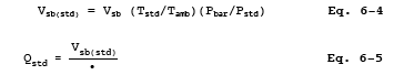
Qstd = Volumetric flow rate through critical orifice, scm/min (scf/min).
_
Qstd = Average flow rate of pre-test and post-test calibration runs, scm/min (scf/min).
Tamb = Ambient absolute temperature of air, K (R).
Vsb = Volume of gas as measured by the soap bubble meter, m3 (ft3).
Vsb(std)= Volume of gas as measured by the soap bubble meter, corrected to standard conditions, scm (scf).
2 = Soap bubble travel time, min.
2s = Time, min.
16.2 Critical Orifices for Volume and Rate Measurements.
A critical orifice may be used in place of the DGM specified in Section 6.1.1.10, provided that it is selected, calibrated, and used as follows:
16.2.1 Preparation of Sampling train.
Assemble the sampling train as shown in Figure 6-2. The rate meter and surge tank are optional but are recommended in order to detect changes in the flow rate.
NOTE: The critical orifices can be adapted to a Method 6 type sampling train as follows: Insert sleeve type, serum bottle stoppers into two reducing unions. Insert the needle into the stoppers as shown in Figure 6-3.
16.2.2 Selection of Critical Orifices.
16.2.2.1 The procedure that follows describes the use of hypodermic needles and stainless steel needle tubings, which have been found suitable for use as critical orifices. Other materials and critical orifice designs may be used provided the orifices act as true critical orifices, (i.e., a critical vacuum can be obtained) as described in this section. Select a critical orifice that is sized to operate at the desired flow rate. The needle sizes and tubing lengths shown in Table 6-1 give the following approximate flow rates.
16.2.2.2 Determine the suitability and the appropriate operating vacuum of the critical orifice as follows: If applicable, temporarily attach a rate meter and surge tank to the outlet of the sampling train, if said equipment is not present (see Section 16.2.1). Turn on the pump and adjust the valve to give an outlet vacuum reading corresponding to about half of the atmospheric pressure. Observe the rate meter reading. Slowly increase the vacuum until a stable reading is obtained on the rate meter. Record the critical vacuum, which is the outlet vacuum when the rate meter first reaches a stable value. Orifices that do not reach a critical value must not be used.
16.2.3 Field Procedures.
16.2.3.1 Leak-Check Procedure. A leak-check before the sampling run is recommended, but not required. The leak-check procedure is as follows: Temporarily attach a suitable (e.g., 0-40 ml/min) rotameter and surge tank, or a soap bubble meter and surge tank to the outlet of the pump. Plug the Probe inlet, pull an outlet vacuum of at least 250 mm Hg (10 in. Hg), and note the flow rate as indicated by the rotameter or bubble meter. A leakage rate in excess of 2 percent of the average sampling rate (Qstd) is not acceptable. Carefully release the Probe inlet plug before turning off the pump.
16.2.3.2 Moisture Determination. At the sampling location, prior to testing, determine the percent moisture of the ambient air using the wet and dry bulb temperatures or, if appropriate, a relative humidity meter.
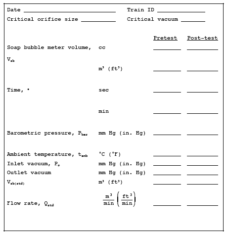
16.2.3.3 Critical Orifice calibration. At the sampling location, prior to testing, calibrate the entire sampling train (i.e., determine the flow rate of the sampling train when operated at critical conditions). Attach a 500-ml soap bubble meter to the inlet of the Probe, and operate the sampling train at an outlet vacuum of 25 to 50 mm Hg (1 to 2 in. Hg) above the critical vacuum. Record the information listed in Figure 6-4. Calculate the standard volume of air measured by the soap bubble meter and the volumetric flow rate using the equations below:
16.2.3.4 Sampling.
16.2.3.4.1 Operate the sampling train for sample collection at the same vacuum used during the calibration run. Start the watch and pump simultaneously. Take readings (temperature, rate meter, inlet vacuum, and outlet vacuum) at least every 5 minutes. At the end of the sampling run, stop the watch and pump simultaneously.
16.2.3.4.2 Conduct a post-test calibration run using the calibration procedure outlined in Section 16.2.3.3. If the Qstd obtained before and after the test differ by more than 5 percent, void the test run; if not, calculate the volume of the gas measured with the critical orifice using Equation 6-6 as follows:
![]()
16.2.3.4.3 If the percent difference between the molecular weight of the ambient air at saturated conditions and the sample gas is more that ± 3 percent, then the molecular weight of the gas sample must be considered in the calculations using the following equation:
![]()
NOTE: A post-test leak-check is not necessary because the post-test calibration run results will indicate whether there is any leakage.
16.2.3.4.4 Drain the ice bath, and purge the sampling train using the procedure described in Section 8.3.4.
16.3 Elimination of Ammonia Interference.
The following alternative procedures must be used in addition to those specified in the method when sampling at sources having ammonia emissions.
16.3.1 Sampling.
The Probe shall be maintained at 275C (527F) and equipped with a high-efficiency in-stack filter (glass fiber) to remove particulate matter. The filter material shall be unreactive to SO2. Whatman 934AH (formerly Reeve Angel 934AH) filters treated as described in Reference 10 in Section 17.0 of Method 5 is an example of a filter that has been shown to work. Where alkaline particulate matter and condensed moisture are present in the gas stream, the filter shall be heated above the moisture dew point but below 225C (437F).
16.3.2 Sample Recovery.
Recover the sample according to Section 8.4 except for discarding the contents of the midget bubbler. Add the bubbler contents, including the rinsings of the bubbler with water, to a separate polyethylene bottle from the rest of the sample. Under normal testing conditions where sulfur trioxide will not be present significantly, the tester may opt to delete the midget bubbler from the sampling train. If an approximation of the sulfur trioxide concentration is desired, transfer the contents of the midget bubbler to a separate polyethylene bottle.
16.3.3 Sample Analysis.
Follow the procedures in Sections 11.1 and 11.2, except add 0.5 ml of 0.1 N HCl to the Erlenmeyer flask and mix before adding the indicator. The following analysis procedure may be used for an approximation of the sulfur trioxide concentration. The accuracy of the calculated concentration will depend upon the ammonia to SO2 ratio and the level of oxygen present in the gas stream. A fraction of the SO2 will be counted as sulfur trioxide as the ammonia to SO2 ratio and the sample oxygen content increases. Generally, when this ratio is 1 or less and the oxygen content is in the range of 5 percent, less than 10 percent of the SO2 will be counted as sulfur trioxide. Analyze the peroxide and isopropanol sample portions separately. Analyze the peroxide portion as described above. Sulfur trioxide is determined by difference using sequential titration of the isopropanol portion of the sample. Transfer the contents of the isopropanol storage container to a 100-ml volumetric flask, and dilute to exactly 100 ml with water. Pipette a 20-ml aliquot of this solution into a 250-ml Erlenmeyer flask, add 0.5 ml of 0.1 N HCl, 80 ml of 100 percent isopropanol, and two to four drops of thorin indicator. Titrate to a pink endpoint using 0.0100 N barium perchlorate. Repeat and average the titration volumes that agree within 1 percent or 0.2 ml, whichever is larger. Use this volume in Equation 6-2 to determine the sulfur trioxide concentration. From the flask containing the remainder of the isopropanol sample, determine the fraction of SO2 collected in the bubbler by pipetting 20-ml aliquots into 250-ml Erlenmeyer flasks. Add 5 ml of 3 percent H2O2, 100 ml of 100 percent isopropanol, and two to four drips of thorin indicator, and titrate as before. From this titration volume, subtract the titrant volume determined for sulfur trioxide, and add the titrant volume determined for the peroxide portion. This final volume constitutes Vt, the volume of barium perchlorate used for the SO2 sample.
17.0 References.
1. Atmospheric Emissions from Sulfuric Acid Manufacturing Processes. U.S. DHEW, PHS, Division of Air Pollution. Public Health Service Publication No. 999-AP-13. Cincinnati, OH. 1965.
2. Corbett, P.F. The Determination of SO2 and SO3 in flue Gases. Journal of the Institute of Fuel. 24:237-243.1961.
3. Matty, R.E., and E.K. Diehl. Measuring flue-Gas SO2 and SO3. Power. 101:94-97. November 1957.
4. Patton, W.F., and J.A. Brink, Jr. New equipment and Techniques for Sampling Chemical Process Gases. J. Air Pollution Control Association. 13:162. 1963.
5. Rom, J.J. Maintenance, calibration, and Operation of Isokinetic Source Sampling equipment. Office of Air Programs, U.S. Environmental Protection Agency. Research Triangle Park, NC. APTD-0576. March 1972.
6. Hamil, H.F., and D.E. Camann. Collaborative Study of Method for the Determination of Sulfur Dioxide Emissions from Stationary Sources (Fossil-Fuel Fired Steam Generators). U.S. Environmental Protection Agency, Research Triangle Park, NC. EPA-650/4-74-024. December 1973.
7. Annual Book of ASTM Standards. Part 31; Water, Atmospheric Analysis. American Society for Testing and Materials. Philadelphia, PA. 1974. pp. 40-42.
8. Knoll, J.E., and M.R. Midgett. The Application of EPA Method 6 to High Sulfur Dioxide Concentrations. U.S. Environmental Protection Agency. Research Triangle Park, NC. EPA-600/4-76-038. July 1976.
9. Westlin, P. R., and R. T. Shigehara. Procedure for Calibrating and Using Dry Gas Volume meters as calibration Standards. Source Evaluation Society Newsletter. 3(1):17-30. February 1978.
10. Yu, K. K. Evaluation of Moisture Effect on dry gas meter calibration. Source Evaluation Society
Newsletter. 5(1):24-28. February 1980.
11. Lodge, J.P., Jr., et al. The Use of Hypodermic Needles as Critical Orifices in Air Sampling. J. Air Pollution Control Association. 16:197-200. 1966.
12. Shigehara, R.T., and C.B. Sorrell. Using Critical Orifices as Method 5 calibrationStandards. Source Evaluation Society Newsletter. 10:4-15. August 1985.
13. Curtis, F., Analysis of Method 6 Samples in the Presence of Ammonia. Source Evaluation Society Newsletter. 13(1):9-15 February 1988.
18.0 Tables, Diagrams, flowcharts and Validation Data.
TABLE 6-1. APPROXIMATE flow RATES FOR VARIOUS NEEDLE SIZES.
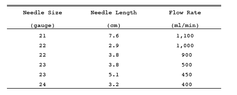
Figure 6-1. Sulfur Dioxide Sampling train.
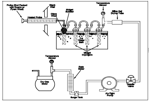
Figure 6-2. Sulfur Dioxide Sampling train Using a Critical Orifice.
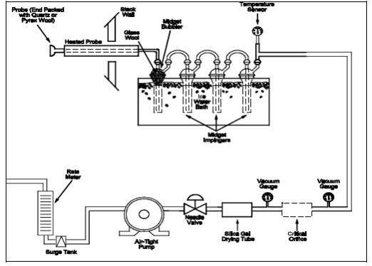
Figure 6-3. Critical Orifice Adaptation for the Method 6 Sampling train.
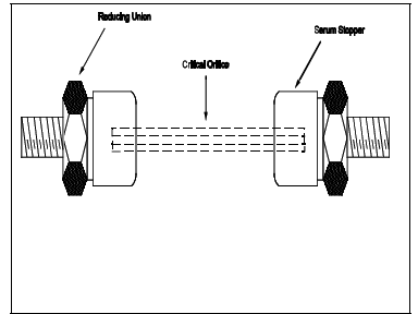
Figure 6-4. Critical Orifice calibration Data Sheet.
- Analytical
- Ion Chromatography
- Gas Chromatography
- Gravimetrics
- Ash Resistivity
- Inks/Coatings
- Scrubber Stoichiometry
- Titrations
- Mercury Sorbent Trap
- Engineering
- Express Products
- Rental Instruments
- MET80 Mercury Monitor
- Continuous Emission Monitors
- Gas Sampling Equipment
- Mobile Power Supply
Our Resources
- Technical Resources