- Home
- Careers
- Contact
- About
-
Who we are and what we do. -
Press releases, announcements, and notable corporate information. -
We are looking for a few A people. -
We have over 40 years of innovation to create value for our customers. -
We aim to be the highest value provider of every product and service we offer. -
An easy guide to Probe fundamentals.
-
- Services
-
In additional to the analytical results we normally include an expert analysts summary.
We use our decades of experience to help you better understand your data. -
CleanAir can insures that the project goals and testing are objectives are met.
-
We can ship what you need today. It will work. You get a company of experts when you rent from CleanAir. - Thermal Performance
-
- Rental
-
Our factory reconditioning experts work to make old as good as new. -
CleanAir can provide the services required to care of your emissions measurement or power measurement instruments, no matter the age, model or manufacturer.
-
We deliver rental, emergency, or supplemental instruments and onsite services quickly, with minimal operational interruptions .
-
- Products
Featured Product

UL Listed Mobile Temporary Power
Look professional. Don't risk a OSHA fine, or worse causing your customer to get an OSHA or MSHA fine by using an unsafe mobile power distribution system. The CleanAir Temporary Power cart is UL listed! Read more... -
Reference
-
Overviews of products and services -
Learn about our companies and business -
Detailed technical information about the functioning of our products -
Guides and instructions on proper installation and service -
Guides and instructions on proper installation and service -
Drawings, configuration, materials, and limits useful for the planning and layout.
-
CleanAir's reference of video content -
Publications addressing an issue or topic
-
- Site Map
 Express
 FTIR
FTIR Mercury
 Emission Sampling Equipment
 Instrument Rental
EPA Methods List with Links
US EPA Method 108 - Determination Of Particulate And Gaseous Arsenic Emissions
NOTE: This method does not include all of the specifications (e.g., equipment and supplies) and procedures (e.g., sampling and analytical) essential to its performance. Some material is incorporated by reference from other methods in Appendix A to 40 CFR Part 60. Therefore, to obtain reliable results, persons using this method should have a thorough knowledge of at least the following additional test methods: Method 1, Method 2, Method 3, Method 5, and Method 12.
Content [ show/hide ].1.0 Scope and Application.
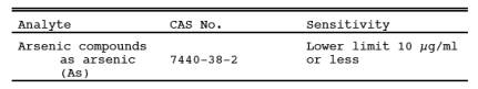
1.1 Analytes.
1.2 Applicability.
This method is applicable for the determination of inorganic As emissions from stationary sources as specified in an applicable subpart of the regulations.
1.3 Data Quality Objectives.
Adherence to the requirements of this method will enhance the quality of the data obtained from air pollutant sampling methods.
2.0 Summary of Method.
Particulate and gaseous As emissions are withdrawn isokinetically from the source and are collected on a glass mat filter and in water. The collected arsenic is then analyzed by means of atomic absorption spectrophotometry (AAS).
3.0 Definitions. [Reserved]
4.0 Interferences.
Analysis for As by flame AAS is sensitive to the chemical composition and to the physical properties (e.g., viscosity, pH) of the sample. The analytical procedure includes a check for matrix effects (Section 11.5).
5.0 Safety.
5.1 This method may involve hazardous materials, operations, and equipment. This test method may not address all of the safety problems associated with its use. It is the responsibility of the user to establish appropriate safety and health practices and determine the applicability of regulatory limitations prior to performing this test method.
5.2 Corrosive reagents. The following reagents are hazardous. Personal protective equipment and safe procedures that prevent chemical splashes are recommended. If contact occurs, immediately flush with copious amounts of water for at least 15 minutes. Remove clothing under shower and decontaminate. Treat residual chemical burns as thermal burns.
5.2.1 Hydrochloric Acid (HCl). Highly corrosive liquid with toxic vapors. Vapors are highly irritating to eyes, skin, nose, and lungs, causing severe damage. May cause bronchitis, pneumonia, or edema of lungs. Exposure to concentrations of 0.13 to 0.2 percent can be lethal to humans in a few minutes. Provide ventilation to limit exposure. Reacts with metals, producing hydrogen gas.
5.2.2 Hydrogen Peroxide (H2O2). Very harmful to eyes. 30% H2O2 can burn skin, nose, and lungs.
5.2.3 Nitric Acid (HNO3). Highly corrosive to eyes, skin, nose, and lungs. Vapors are highly toxic and can cause bronchitis, pneumonia, or edema of lungs. Reaction to inhalation may be delayed as long as 30 hours and still be fatal. Provide ventilation to limit exposure. Strong oxidizer. Hazardous reaction may occur with organic materials such as solvents.
5.2.4 Sodium Hydroxide (NaOH). Causes severe damage to eyes and skin. Inhalation causes irritation to nose, throat, and lungs. Reacts exothermically with small amounts of water.
6.0 Equipment and Supplies.
6.1 Sample Collection.
A schematic of the sampling train used in performing this method is shown in Figure 108-1; it is similar to the Method 5 sampling train of 40 CFR Part 60, Appendix A. The following items are required for sample collection:
6.1.1 Probe nozzles, Probe Liner, pitot Tube, Differential Pressure Gauge, filter Holder, filter Heating System, temperature sensor, metering System, barometer, and Gas Density Determination equipment. Same as Method 5, Sections 6.1.1.1 to 6.1.1.7, 6.1.1.9, 6.1.2, and 6.1.3, respectively.
6.1.2 impingers. Four impingers connected in series with leak-free ground-glass fittings or any similar leak-free noncontaminating fittings. For the first, third, and fourth impingers, use the Greenburg-Smith design, modified by replacing the tip with a 1.3-cm ID (0.5-in.) glass tube extending to about 1.3 cm (0.5 in.) from the bottom of the flask. For the second impinger, use the Greenburg-Smith design with the standard tip. Modifications (e.g., flexible connections between the impingers, materials other than glass, or flexible vacuum lines to connect the filter holder to the condenser) are subject to the approval of the Administrator.
6.1.3 temperature sensor. Place a temperature sensor, capable of measuring temperature to within 1 °C (2 °F), at the outlet of the fourth impinger for monitoring purposes.
6.2 Sample Recovery.
The following items are required for sample recovery:
6.2.1 Probe-Liner and Probe-nozzles Brushes, Petri Dishes, Graduated Cylinder and/or Balance, Plastic Storage Containers, and Funnel and Rubber Policeman. Same as Method 5, Sections 6.2.1 and 6.2.4 to 6.2.8, respectively.
6.2.2 Wash Bottles. Polyethylene (2).
6.2.3 Sample Storage Containers. Chemically resistant, polyethylene or polypropylene for glassware washes, 500- or 1000-ml.
6.3 Analysis.
The following items are required for analysis:
6.3.1 Spectrophotometer. Equipped with an electrodeless discharge lamp and a background corrector to measure absorbance at 193.7 nanometers (nm). For measuring samples having less than 10 g As/ml, use a vapor generator accessory or a graphite furnace.
6.3.2 Recorder. To match the output of the spectrophotometer.
6.3.3 Beakers. 150 ml.
6.3.4 Volumetric Flasks. glass 50-, 100-, 200-, 500-, and 1000-ml; and polypropylene, 50-ml.
6.3.5 Balance. To measure within 0.5 g.
6.3.6 Volumetric Pipets. 1-, 2-, 3-, 5-, 8-, and 10-ml.
6.3.7 oven.
6.3.8 Hot Plate.
7.0 Reagents and Standards.
Unless otherwise indicated, it is intended that all reagents conform to the specifications established by the Committee on Analytical Reagents of the American Chemical Society, where such specifications are available; otherwise, use the best available grade.
7.1 Sample Collection
The following reagents are required for sample collection:
7.1.1 filters. Same as Method 5, Section 7.1.1, except that the filters need not be unreactive to SO2.
7.1.2 Silica Gel, Crushed Ice, and Stopcock Grease. Same as Method 5, Sections 7.1.2, 7.1.4, and 7.1.5, respectively.
7.1.3 Water. Deionized distilled to meet ASTM D 1193-77 or 91 (incorporated by reference)see § 61.18), Type 3. When high concentrations of organic matter are not expected to be present, the KMnO4 test for oxidizable organic matter may be omitted.
7.2 Sample Recovery.
7.2.1 0.1 N NaOH. Dissolve 4.00 g of NaOH in about 500 ml of water in a 1-liter volumetric flask. Then, dilute to exactly 1.0 liter with water.
7.3 Analysis.
The following reagents and standards are required for analysis:
7.3.1 Water. Same as Section 7.1.3.
7.3.2 Sodium Hydroxide, 0.1 N. Same as in Section 7.2.1.
7.3.3 Sodium Borohydride (NaBH4), 5 Percent Weight by Volume (W/V). Dissolve 50.0 g of NaBH4 in about 500 ml of 0.1 N NaOH in a 1-liter volumetric flask. Then, dilute to exactly 1.0 liter with 0.1 N NaOH.
7.3.4 Hydrochloric Acid, Concentrated.
7.3.5 Potassium Iodide (KI), 30 Percent (W/V). Dissolve 300 g of KI in 500 ml of water in a 1 liter volumetric flask. Then, dilute to exactly 1.0 liter with water.
7.3.6 Nitric Acid, Concentrated.
7.3.7 Nitric Acid, 0.8 N. Dilute 52 ml of concentrated HNO3 to exactly 1.0 liter with water.
7.3.8 Nitric Acid, 50 Percent by Volume (V/V). Add 50 ml concentrated HNO3 to 50 ml water.
7.3.9 Stock Arsenic Standard, 1 mg As/ml. Dissolve 1.3203 g of primary standard grade As2O3 in 20 ml of 0.1 N NaOH in a 150 ml beaker. Slowly add 30 ml of concentrated HNO3. Heat the resulting solution and evaporate just to dryness. Transfer the residue quantitatively to a 1-liter volumetric flask, and dilute to 1.0 liter with water.
7.3.10 Arsenic Working Solution, 1.0 g As/ml. Pipet exactly 1.0 ml of stock arsenic standard into an acid-cleaned, appropriately labeled 1-liter volumetric flask containing about 500 ml of water and 5 ml of concentrated HNO3. Dilute to exactly 1.0 liter with water.
7.3.11 Air. Suitable quality for AAS analysis.
7.3.12 Acetylene. Suitable quality for AAS analysis.
7.3.13 Nickel Nitrate, 5 Percent Ni (W/V). Dissolve 24.780 g of nickel nitrate hexahydrate [Ni(NO3)26H2O] in water in a 100-ml volumetric flask, and dilute to 100 ml with water.
7.3.14 Nickel Nitrate, 1 Percent Ni (W/V). Pipet 20 ml of 5 percent nickel nitrate solution into a 100-ml volumetric flask, and dilute to exactly 100 ml with water.
7.3.15 Hydrogen Peroxide, 3 Percent by Volume. Pipet 50 ml of 30 percent H2O2 into a 500-ml volumetric flask, and dilute to exactly 500 ml with water.
7.3.16 Quality Assurance Audit Samples. When making compliance determinations, and upon availability, audit samples may be obtained from the appropriate EPA regional Office or from the responsible enforcement authority.
NOTE: The responsible enforcement authority should be notified at least 30 days prior to the test date to allow sufficient time for sample delivery.
8.0 Sample Collection, Preservation, Transport, and Storage.
8.1 Pretest Preparation. Follow the general procedure given in Method 5, Section 8.1, except the filter need not be weighed, and the 200 ml of 0.1N NaOH and Container 4 should be tared to within 0.5 g.
8.2 Preliminary Determinations. Follow the general procedure given in Method 5, Section 8.2, except select the nozzles size to maintain isokinetic sampling rates below 28 liters/min (1.0 cfm).
8.3 Preparation of Sampling Train. Follow the general procedure given in Method 5, Section 8.3.
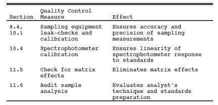
8.4 Leak-Check Procedures. Same as Method 5, Section 8.4.
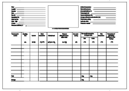
8.5 Sampling Train Operation. Follow the general procedure given in Method 5, Section 8.5, except maintain isokinetic sampling flow rates below 28 liters/min (1.0 cfm). For each run, record the data required on a data sheet similar to the one shown in Figure 108-2.
8.6 Calculation of Percent Isokinetic. Same as Method 5, Section 8.6.
8.7 Sample Recovery. Same as Method 5, Section 8.7, except that 0.1 N NaOH is used as the cleanup solvent instead of acetone and that the impinger water is treated as follows:
8.7.1 Container Number 4 (impinger Water). Clean each of the first three impingers and connecting glassware in the following manner:
8.7.1.1 Wipe the impinger ball joints free of silicone grease, and cap the joints.
8.7.1.2 Rotate and agitate each of the first two impingers, using the impinger contents as a rinse solution.
8.7.1.3 Transfer the liquid from the first three impingers to Container Number 4. Remove the outlet ball-joint cap, and drain the contents through this opening. Do not separate the impinger parts (inner and outer tubes) while transferring their contents to the container.
8.7.1.4 Weigh the contents of Container No. 4 to within 0.5 g. Record in the log the weight of liquid along with a notation of any color or film observed in the impinger catch. The weight of liquid is needed along with the silica gel data to calculate the stack gas moisture content.
NOTE: Measure and record the total amount of 0.1 N NaOH used for rinsing under Sections 8.7.1.5 and 8.7.1.6.
8.7.1.5 Pour approximately 30 ml of 0.1 NaOH into each of the first two impingers, and agitate the impingers. Drain the 0.1 N NaOH through the outlet arm of each impinger into Container Number 4. Repeat this operation a second time; inspect the impingers for any abnormal conditions.
8.7.1.6 Wipe the ball joints of the glassware connecting the impingers and the back half of the filter holder free of silicone grease, and rinse each piece of glassware twice with 0.1 N NaOH; transfer this rinse into Container Number 4. (DO NOT RINSE or brush the glass-fritted filter support.) Mark the height of the fluid level to determine whether leakage occurs during transport. Label the container to identify clearly its contents.
8.8 Blanks.
8.8.1 Sodium Hydroxide. Save a portion of the 0.1 N NaOH used for cleanup as a blank. Take 200 ml of this solution directly from the wash bottle being used and place it in a plastic sample container labeled "NaOH blank."
8.8.2 Water. Save a sample of the water, and place it in a container labeled "H2O blank."
8.8.3 filter. Save two filters from each lot of filters used in sampling. Place these filters in a container labeled "filter blank."
9.0 Quality Control.
9.1 Miscellaneous Quality Control Measures.
9.2 Volume metering System Checks. Same as Method 5, Section 9.2.
10.0 Calibration and Standardization.
NOTE: Maintain a laboratory log of all calibrations.
10.1 Sampling equipment.
Same as Method 5, Section 10.0.
10.2 Preparation of Standard Solutions.
10.2.1 For the high level procedure, pipet 1, 3, 5, 8, and 10 ml of the 1.0 mg As/ml stock solution into separate 100 ml volumetric flasks, each containing 5 ml of concentrated HNO3. Dilute to the mark with water.
10.2.2 For the low level vapor generator procedure, pipet 1, 2, 3, and 5 ml of 1.0 g As/ml standard solution into separate reaction tubes. Dilute to the mark with water.
10.2.3 For the low level graphite furnace procedure,pipet 1, 5, 10 and 15 ml of 1.0 g As/ml standard solution into separate flasks along with 2 ml of the 5 percent nickel nitrate solution and 10 ml of the 3 percent H20>2 solution. Dilute to the mark with water.
10.3 calibration Curve.
Analyze a 0.8 N HNO3 blank and each standard solution according to the procedures outlined in Section 11.4.1. Repeat this procedure on each standard solution until two consecutive peaks agree within 3 percent of their average value. Subtract the average peak height (or peak area) of the blank - which must be less than 2 percent of recorder full scale - from the averaged peak height of each standard solution. If the blank absorbance is greater than 2 percent of full-scale, the probable cause is As contamination of a reagent or carry-over of As from a previous sample. Prepare the calibration curve by plotting the corrected peak height of each standard solution versus the corresponding final total As weight in the solution.
10.4 Spectrophotometer calibration Quality Control.
Calculate the least squares slope of the calibration curve. The line must pass through the origin or through a point no further from the origin than ±2 percent of the recorder full scale. Multiply the corrected peak height by the reciprocal of the least squares slope to determine the distance each calibration point lies from the theoretical calibration line. The difference between the calculated concentration values and the actual concentrations (e.g., 1, 3, 5, 8, and 10 mg As for the high-level procedure) must be less than 7 percent for all standards.
NOTE: For instruments equipped with direct concentration readout devices, preparation of a standard curve will not be necessary. In all cases, follow calibration and operational procedures in the manufacturers' instruction manual.
11.0 Analytical Procedure.
11.1 Sample Loss Check.
Prior to analysis, check the liquid level in Containers Number 2 and Number 4. Note on the analytical data sheet whether leakage occurred during transport. If a noticeable amount of leakage occurred, either void the sample or take steps, subject to the approval of the Administrator, to adjust the final results.
11.2 Sample Preparation.
11.2.1 Container Number 1 (Filter). Place the filter and loose particulate matter in a 150 ml beaker. Also, add the filtered solid material from Container Number 2 (see Section 11.2.2). Add 50 ml of 0.1 N NaOH. Then stir and warm on a hot plate at low heat (do not boil) for about 15 minutes. Add 10 ml of concentrated HNO3, bring to a boil, then simmer for about 15 minutes. filter the solution through a glass fiber filter. Wash with hot water, and catch the filtrate in a clean 150 ml beaker. Boil the filtrate, and evaporate to dryness. Cool, add 5 ml of 50 percent HNO3, and then warm and stir. Allow to cool. Transfer to a 50-ml volumetric flask, dilute to volume with water, and mix well.
11.2.2 Container Number 2 (Probe Wash).
11.2.2.1 filter (using a glass fiber filter) the contents of Container Number 2 into a 200 ml volumetric flask. Combine the filtered (solid) material with the contents of Container Number 1 (filter).
11.2.2.2 Dilute the filtrate to exactly 200 ml with water. Then pipet 50 ml into a 150 ml beaker. Add 10 ml of concentrated HNO3, bring to a boil, and evaporate to dryness. Allow to cool, add 5 ml of 50 percent HNO3, and then warm and stir. Allow the solution to cool, transfer to a 50-ml volumetric flask, dilute to volume with water, and mix well.
11.2.3 Container Number 4 (impinger Solution). Transfer the contents of Container Number 4 to a 500 ml volumetric flask, and dilute to exactly 500-ml with water. Pipet 50 ml of the solution into a 150-ml beaker. Add 10 ml of concentrated HNO3, bring to a boil, and evaporate to dryness. Allow to cool, add 5 ml of 50 percent HNO3, and then warm and stir. Allow the solution to cool, transfer to a 50-ml volumetric flask, dilute to volume with water, and mix well.
11.2.4 filter Blank. Cut each filter into strips, and treat each filter individually as directed in Section 11.2.1, beginning with the sentence, "Add 50 ml of 0.1 N NaOH."
11.2.5 Sodium Hydroxide and Water Blanks. Treat separately 50 ml of 0.1 N NaOH and 50 ml water, as directed under Section 11.2.3, beginning with the sentence, "Pipet 50 ml of the solution into a 150-ml beaker."
11.3 Spectrophotometer Preparation.
Turn on the power; set the wavelength, slit width, and lamp current. Adjust the background corrector as instructed by the manufacturer's manual for the particular atomic absorption spectrophotometer. Adjust the burner and flame characteristics as necessary.
11.4 Analysis.
Calibrate the analytical equipment and develop a calibration curve as outlined in Sections 10.2 through 10.4
11.4.1 Arsenic Samples. Analyze an appropriately sized aliquot of each diluted sample (from Sections 11.2.1 through 11.2.3) until two consecutive peak heights agree within 3 percent of their average value. If applicable, follow the procedures outlined in Section 11.4.1.1. If the sample concentration falls outside the range of the calibration curve, make an appropriate dilution with 0.8 N HNO3 so that the final concentration falls within the range of the curve. Using the calibration curve, determine the arsenic concentration in each sample fraction.
NOTE: Because instruments vary between manufacturers, no detailed operating instructions will be given here. Instead, the instrument manufacturer's detailed operating instructions should be followed.
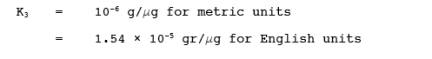
11.4.1.1 Arsenic Determination at Low Concentration. The lower limit of flame AAS is 10 g As/ml. If the arsenic concentration of any sample is at a lower level, use the graphite furnace or vapor generator which is available as an accessory component. Flame, graphite furnace, or vapor generators may be used for samples whose concentrations are between 10 and 30 g/ml. Follow the manufacturer's instructions in the use of such equipment.
11.4.1.1.1 Vapor Generator Procedure. Place a sample containing between 0 and 5 g of arsenic in the reaction tube, and dilute to 15 ml with water. Since there is some trial and error involved in this procedure, it may be necessary to screen the samples by conventional atomic absorption until an approximate concentration is determined. After determining the approximate concentration, adjust the volume of the sample accordingly. Pipet 15 ml of concentrated HCl into each tube. Add 1 ml of 30 percent KI solution. Place the reaction tube into a 50 °C (120 °F) water bath for 5 minutes. Cool to room temperature. Connect the reaction tube to the vapor generator assembly. When the instrument response has returned to baseline, inject 5.0 ml of 5 percent NaBH4, and integrate the resulting spectrophotometer signal over a 30-second time period.
11.4.1.1.2 Graphite Furnace Procedure. Dilute the digested sample so that a 5 ml aliquot contains less than 1.5 g of arsenic. Pipet 5 ml of this digested solution into a 10-ml volumetric flask. Add 1 ml of the 1 percent nickel nitrate solution, 0.5 ml of 50 percent HNO3, and 1 ml of the 3 percent hydrogen peroxide and dilute to 10 ml with water. The sample is now ready for analysis.
11.4.1.2 Run a blank (0.8 N HNO3) and standard at least after every five samples to check the spectrophotometer calibration. The peak height of the blank must pass through a point no further from the origin than ±2 percent of the recorder full scale. The difference between the measured concentration of the standard (the product of the corrected average peak height and the reciprocal of the least squares slope) and the actual concentration of the standard must be less than 7 percent, or recalibration of the analyzer is required.
11.4.1.3 Determine the arsenic concentration in the filter blank (i.e., the average of the two blank values from each lot).
11.4.2 Container Number 3 (Silica Gel). This step may be conducted in the field. Weigh the spent silica gel (or silica gel plus impinger) to the nearest 0.5 g; record this weight.
11.5 Check for matrix effects on the arsenic results.
Same as Method 12, Section 11.5.
11.6 Audit Sample Analysis.
11.6.1 When the method is used to analyze samples to demonstrate compliance with a source emission regulation, a set of EPA audit samples must be analyzed, subject to availability.
11.6.2 Concurrently analyze the audit samples and the compliance samples in the same manner to evaluate the technique of the analyst and the standards preparation.
NOTE: It is recommended that known quality control samples be analyzed prior to the compliance and audit sample analyses to optimize the system accuracy and precision. These quality control samples may be obtained by contacting the appropriate EPA regional Office or the responsible enforcement authority.
11.6.3 The same analyst, analytical reagents, and analytical system shall be used for the compliance samples and the EPA audit samples. If this condition is met, duplicate auditing of subsequent compliance analyses for the same enforcement agency within a 30-day period is waived. An audit sample set may not be used to validate different sets of compliance samples under the jurisdiction of separate enforcement agencies, unless prior arrangements have been made with both enforcement agencies.
11.7 Audit Sample Results.
11.7.1 Calculate the audit sample concentrations in g/m3 and submit results using the instructions provided with the audit samples.
11.7.2 Report the results of the audit samples and the compliance determination samples along with their identification numbers, and the analyst's name to the responsible enforcement authority. Include this information with reports of any subsequent compliance analyses for the same enforcement authority during the 30-day period.
11.7.3 The concentrations of the audit samples obtained by the analyst shall agree within 10 percent of the actual concentrations. If the 10 percent specification is not met, reanalyze the compliance and audit samples, and include initial and reanalysis values in the test report.
11.7.4 Failure to meet the 10 percent specification may require retests until the audit problems are resolved. However, if the audit results do not affect the compliance or noncompliance status of the affected facility, the Administrator may waive the reanalysis requirement, further audits, or retests and accept the results of the compliance test. While steps are being taken to resolve audit analysis problems, the Administrator may also choose to use the data to determine the compliance or noncompliance status of the affected facility.
12.0 Data Analysis and Calculations.
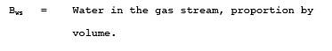
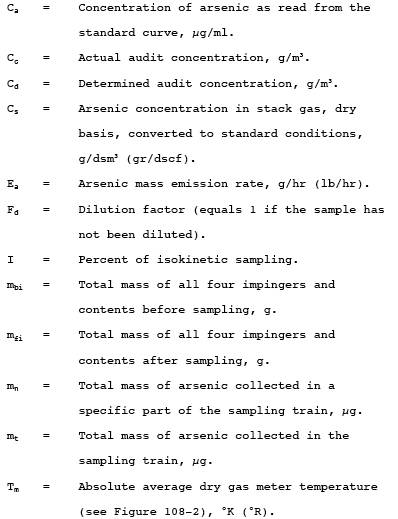
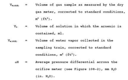
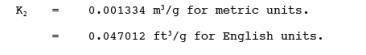
12.1 Nomenclature.
12.2 Average console meter temperatures (Tm) and Average Orifice Pressure Drop (H). See data sheet (Figure 108-2).
12.3 Dry Gas Volume. Using data from this test, calculate Vm(std) according to the procedures outlined in Method 5, Section 12.3.
12.4 Volume of Water Vapor.

where:
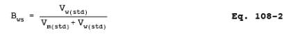
12.5 Moisture Content.
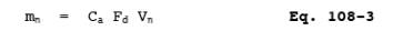
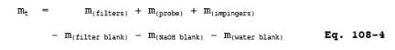
12.6 Amount of Arsenic Collected.
12.6.1 Calculate the amount of arsenic collected in each part of the sampling train, as follows:
12.6.2 Calculate the total amount of arsenic collected in the sampling train as follows:
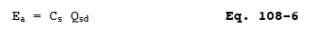
12.7 Calculate the arsenic concentration in the stack gas (dry basis, adjusted to standard conditions) as follows:

where:
12.8 Stack Gas Velocity and Volumetric flow Rate. Calculate the average stack gas velocity and volumetric flow rate using data obtained in this method and the equations in Sections 12.2 and 12.3 of Method 2.
12.9 Pollutant Mass Rate. Calculate the arsenic mass emission rate as follows:
12.10 Isokinetic Variation. Same as Method 5, Section 12.11.
13.0 Method Performance.
13.1 Sensitivity. The lower limit of flame AAS 10 g As/ml. The analytical procedure includes provisions for the use of a graphite furnace or vapor generator for samples with a lower arsenic concentration.
14.0 Pollution Prevention. [Reserved]
15.0 Waste Management. [Reserved]
16.0 References.
Same as References 1 through 9 of Method 5, Section 17.0, with the addition of the following:
1. Perkin Elmer Corporation. Analytical Methods for Atomic Absorption Spectrophotometry. 303-0152. Norwalk, Connecticut. September 1976. pp. 5-6.
2. Standard Specification for Reagent Water. In: Annual Book of American Society for Testing and Materials Standards. Part 31: Water, Atmospheric Analysis. American Society for Testing and Materials. Philadelphia, PA. 1974. pp. 40-42.
3. Stack Sampling Safety Manual (Draft). U.S. Environmental Protection Agency, Office of Air Quality Planning and Standard, Research Triangle Park, NC. September 1978.
17.0 Tables, Diagrams, flowcharts, and Validation Data.
Figure 108-1. Arsenic Sampling Train
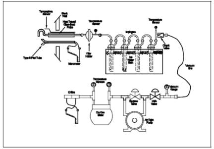
Figure 108-2. Arsenic Field Data Sheet.
- Analytical
- Ion Chromatography
- Gas Chromatography
- Gravimetrics
- Ash Resistivity
- Inks/Coatings
- Scrubber Stoichiometry
- Titrations
- Mercury Sorbent Trap
- Engineering
- Express Products
- Rental Instruments
- MET80 Mercury Monitor
- Continuous Emission Monitors
- Gas Sampling Equipment
- Mobile Power Supply
Our Resources
- Technical Resources