- Home
- Careers
- Contact
- About
-
Who we are and what we do. -
Press releases, announcements, and notable corporate information. -
We are looking for a few A people. -
We have over 40 years of innovation to create value for our customers. -
We aim to be the highest value provider of every product and service we offer. -
An easy guide to Probe fundamentals.
-
- Services
-
In additional to the analytical results we normally include an expert analysts summary.
We use our decades of experience to help you better understand your data. -
CleanAir can insures that the project goals and testing are objectives are met.
-
We can ship what you need today. It will work. You get a company of experts when you rent from CleanAir. - Thermal Performance
-
- Rental
-
Our factory reconditioning experts work to make old as good as new. -
CleanAir can provide the services required to care of your emissions measurement or power measurement instruments, no matter the age, model or manufacturer.
-
We deliver rental, emergency, or supplemental instruments and onsite services quickly, with minimal operational interruptions .
-
- Products
Featured Product

UL Listed Mobile Temporary Power
Look professional. Don't risk a OSHA fine, or worse causing your customer to get an OSHA or MSHA fine by using an unsafe mobile power distribution system. The CleanAir Temporary Power cart is UL listed! Read more... -
Reference
-
Overviews of products and services -
Learn about our companies and business -
Detailed technical information about the functioning of our products -
Guides and instructions on proper installation and service -
Guides and instructions on proper installation and service -
Drawings, configuration, materials, and limits useful for the planning and layout.
-
CleanAir's reference of video content -
Publications addressing an issue or topic
-
- Site Map
 Express
 FTIR
FTIR Mercury
 Emission Sampling Equipment
 Instrument Rental
EPA Methods List with Links
US EPA Method 2 - Determination Of Stack Gas Velocity And Volumetric Flow Rate ( Type S Pitot Tube )
NOTE: This method does not include all of the specifications (e.g., equipment and supplies) and procedures (e.g., sampling) essential to its performance. Some material is incorporated by reference from other methods in this part. Therefore, to obtain reliable results, persons using this method should have a thorough knowledge of at least the following additional test method: Method 1
Content [ show/hide ].1.0 Scope and Application
1.1 This method is applicable for the determination of the average velocity and the volumetric flow rate of a gas stream.
1.2 This method is not applicable at measurement sites that fail to meet the criteria of Method 1, Section 11.1. Also, the method cannot be used for direct measurement in cyclonic or swirling gas streams; Section 11.4 of Method 1 shows how to determine cyclonic or swirling flow conditions. When unacceptable conditions exist, alternative procedures, subject to the approval of the Administrator, must be employed to produce accurate flow rate determinations. Examples of such alternative procedures are: (1) to install straightening vanes; (2) to calculate the total volumetric flow rate stoichiometrically, or (3) to move to another measurement site at which the flow is acceptable.
1.3 Data Quality Objectives. Adherence to the requirements of this method will enhance the quality of the data obtained from air pollutant sampling methods.
2.0 Summary of Method
2.1 The average gas velocity in a stack is determined from the gas density and from measurement of the average velocity head with a Type S (Stausscheibe or reverse type) pitot tube.
3.0 Definitions [Reserved]
4.0 Interferences [Reserved]
5.0 Safety
5.1 Disclaimer
This method may involve hazardous materials, operations, and equipment. This test method may not address all of the safety problems associated with its use. It is the responsibility of the user of this test method to establish appropriate safety and health practices and determine the applicability of regulatory limitations prior to performing this test method.
6.0 Equipment and Supplies
Specifications for the apparatus are given below. Any other apparatus that has been demonstrated (subject to approval of the Administrator) to be capable of meeting the specifications will be considered acceptable.
6.1 Type S Pitot Tube
6.1.1 pitot tube made of metal tubing (e.g., stainless steel)
As shown in Figure 2-1. It is recommended that the external tubing diameter (dimension Dt, Figure 2-2b) be between 0.48 and 0.95 cm (3/16 and 3/8 inch). There shall be an equal distance from the base of each leg of the pitot tube to its face-opening plane (dimensions PA and PB, Figure 2-2b); it is recommended that this distance be between 1.05 and 1.50 times the external tubing diameter. The face openings of the pitot tube shall, preferably, be aligned as shown in Figure 2-2; however, slight misalignments of the openings are permissible (see Figure 2-3).
6.1.2 The Type S Pitot Tube shall have a known coefficient
Determined as outlined in Section 10.0. An identification number shall be assigned to the pitot tube; this number shall be permanently marked or engraved on the body of the tube. A standard pitot tube may be used instead of a Type S, provided that it meets the specifications of Sections 6.7 and 10.2. Note, however, that the static and impact pressure holes of standard pitot tube s are susceptible to plugging in particulate-laden gas streams. Therefore, whenever a standard pitot tube is used to perform a traverse, adequate proof must be furnished that the openings of the pitot tube have not plugged up during the traverse period. This can be accomplished by comparing the velocity head (Δp) measurement recorded at a selected traverse point (readable Δp value) with a second Δp measurement recorded after "back purging" with pressurized air to clean the impact and static holes of the standard pitot tube . If the before and after Δp measurements are within 5 percent, then the traverse data are acceptable. Otherwise, the data should be rejected and the traverse measurements redone. Note that the selected traverse point should be one that demonstrates a readable Δp value. If "back purging" at regular intervals is part of a routine procedure, then comparative Δp measurements shall be conducted as above for the last two traverse points that exhibit suitable Δp measurements.
6.2 Differential Pressure Gauge
An inclined manometer or equivalent device. Most sampling trains are equipped with a 10 in. (water column) inclined-vertical manometer, having 0.01 in. H2O divisions on the 0 to 1 in. inclined scale, and 0.1 in. H2O divisions on the 1 to 10 in. vertical scale. This type of manometer (or other gauge of equivalent sensitivity) is satisfactory for the measurement of Δp values as low as 1.27 mm (0.05 in.) H2O. However, a differential pressure gauge of greater sensitivity shall be used (subject to the approval of the Administrator), if any of the following is found to be true: (1) the arithmetic average of all Δp readings at the traverse points in the stack is less than 1.27 mm (0.05 in.) H2O; (2) for traverses of 12 or more points, more than 10 percent of the individual Δp readings are below 1.27 mm (0.05 in.) H2O; or (3) for traverses of fewer than 12 points, more than one Δp reading is below 1.27 mm (0.05 in.) H20. Reference 18 (see Section 17.0) describes commercially available instrumentation for the measurement of low-range gas velocities.
6.2.1 As an alternative to criteria (1) through (3) above, Equation 2-1 (Section 12.2) may be used to determine the necessity of using a more sensitive differential pressure gauge. If T is greater than 1.05, the velocity head data are unacceptable and a more sensitive differential pressure gauge must be used.
NOTE: If differential pressure gauges other than inclined manometers are used (e.g., magnehelic gauges), their calibration must be checked after each test series. To check the calibration of a differential pressure gauge, compare Δp readings of the gauge with those of a gauge-oil manometer at a minimum of three points, approximately representing the range of Δp values in the stack. If, at each point, the values of Δp as read by the differential pressure gauge and gauge-oil manometer agree to within 5 percent, the differential pressure gauge shall be considered to be in proper calibration. Otherwise, the test series shall either be voided, or procedures to adjust the measured Δp values and final results shall be used, subject to the approval of the Administrator.
6.3 Temperature Sensor
A thermocouple, liquid-filled bulb thermometer, bimetallic thermometer, mercury-in glass thermometer, or other gauge capable of measuring temperatures to within 1.5 percent of the minimum absolute stack temperature. The Temperature Sensor shall be attached to the pitot tube such that the sensor tip does not touch any metal; the gauge shall be in an interference-free arrangement with respect to the pitot tube face openings (see Figure 2-1 and Figure 2-4). Alternative positions may be used if the pitot tube-temperature gauge system is calibrated according to the procedure of Section 10.0. Provided that a difference of not more than 1 percent in the average velocity measurement is introduced, the temperature gauge need not be attached to the pitot tube. This alternative is subject to the approval of the Administrator.
6.4 Pressure Probe and Gauge
A piezometer tube and mercury or water-filled U-tube manometer capable of measuring stack pressure to within 2.5 mm (0.1 in.) Hg. The static tap of a standard type pitot tube or one leg of a Type S Pitot Tube with the face opening planes positioned parallel to the gas flow may also be used as the pressure Probe.
6.5 barometer
A mercury, aneroid, or other barometer capable of measuring atmospheric pressure to within 2.54 mm (0.1 in.) Hg.
NOTE: The barometric pressure reading may be obtained from a nearby National Weather Service station. In this case, the station value (which is the absolute barometric pressure) shall be requested and an adjustment for elevation differences between the weather station and sampling point shall be made at a rate of minus 2.5 mm (0.1 in.) Hg per 30 m (100 ft.) elevation increase or plus 2.5 mm (0.1 in.) Hg per 30 m (100 ft.) for elevation decrease.
6.6 Gas Density Determination equipment
Method 3 equipment, if needed (see Section 8.6), to determine the stack gas dry molecular weight, and Method 4 (reference method) or Method 5 equipment for moisture content determination. Other methods may be used subject to approval of the Administrator.
6.7 Calibration Pitot Tube
When calibration of the Type S Pitot Tube is necessary (see Section 10.1), a standard pitot tube shall be used for a reference. The standard pitot tube shall, preferably, have a known coefficient, obtained either (1) directly from the National Institute of Standards and Technology (NIST), Gaithersburg MD 20899, (301) 975-2002, or (2) by calibration against another standard pitot tube with an NIST-traceable coefficient. Alternatively, a standard pitot tube designed according to the criteria given in Sections 6.7.1 through 6.7.5 below and illustrated in Figure 2-5 (see also References 7, 8, and 17 in Section 17.0) may be used. pitot tubes designed according to these specifications will have baseline coefficients of 0.99 ± 0.01.
6.7.1 Standard Pitot Design
6.7.1.1 Hemispherical (shown in Figure 2-5), ellipsoidal, or conical tip.
6.7.1.2 A minimum of six diameters straight run (based upon D, the external diameter of the tube) between the tip and the static pressure holes.
6.7.1.3 A minimum of eight diameters straight run between the static pressure holes and the centerline of the external tube, following the 90 bend.
6.7.1.4 Static pressure holes of equal size (approximately 0.1 D), equally spaced in a piezometer ring configuration.
6.7.1.5 90 bend, with curved or mitered junction.
6.8 Differential Pressure Gauge for Type S Pitot Tube Calibration
An inclined manometer or equivalent. If the single-velocity calibration technique is employed (see Section 10.1.2.3), the calibration differential pressure gauge shall be readable to the nearest 0.127 mm (0.005 in.) H2O. For multivelocity calibrations, the gauge shall be readable to the nearest 0.127 mm (0.005 in.) H20 for Δp values between 1.27 and 25.4 mm (0.05 and 1.00 in.) H2O, and to the nearest 1.27 mm (0.05 in.) H2O for Δp values above 25.4 mm (1.00 in.) H2O. A special, more sensitive gauge will be required to read Δp values below 1.27 mm (0.05 in.) H20 (see Reference 18 in Section 16.0).
7.0 Reagents and Standards [Reserved]
8.0 Sample Collection and Analysis
8.1 Set up the apparatus as shown in Figure 2-1
Capillary tubing or surge tanks installed between the manometer and pitot tube may be used to dampen Δp fluctuations. It is recommended, but not required, that a pretest leak-check be conducted as follows: (1) blow through the pitot impact opening until at least 7.6 cm (3.0 in.) H20 velocity head registers on the manometer; then, close off the impact opening. The pressure shall remain stable for at least 15 seconds; (2) do the same for the static pressure side, except using suction to obtain the minimum of 7.6 cm (3.0 in.) H2O. Other leak-check procedures, subject to the approval of the Administrator, may be used.
8.2 Level and zero the manometer
Because the manometer level and zero may drift due to vibrations and temperature changes, make periodic checks during the traverse (at least once per hour). Record all necessary data on a form similar to that shown in Figure 2-6.
8.3 Measure the velocity head and temperature at the traverse points specified by Method 1
Ensure that the proper differential pressure gauge is being used for the range of Δp values encountered (see Section 6.2). If it is necessary to change to a more sensitive gauge, do so, and remeasure the Δp and temperature readings at each traverse point. Conduct a post-test leak-check (mandatory), as described in Section 8.1 above, to validate the traverse run.
8.4 Measure the static pressure in the stack. One reading is usually adequate
8.5 Determine the atmospheric pressure
8.6 Determine the stack gas dry molecular weight
For combustion processes or processes that emit essentially CO2, O2, CO, and N2, use Method 3. For processes emitting essentially air, an analysis need not be conducted; use a dry molecular weight of 29.0. For other processes, other methods, subject to the approval of the Administrator, must be used.
8.7 Obtain the moisture content from Method 4 (reference method, or equivalent) or from Method 5
8.8 Determine the cross-sectional area of the stack or duct at the sampling location
Whenever possible, physically measure the stack dimensions rather than using blueprints. Do not assume that stack diameters are equal. Measure each diameter distance to verify its dimensions.
9.0 Quality Control
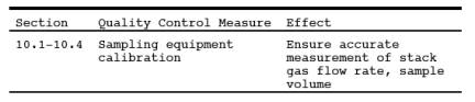
10.0 Calibration and Standardization
10.1 Type S Pitot Tube
Before its initial use, carefully examine the Type S Pitot Tube top, side, and end views to verify that the face openings of the tube are aligned within the specifications illustrated in Figures 2-2 and 2-3. The pitot tube shall not be used if it fails to meet these alignment specifications. After verifying the face opening alignment, measure and record the following dimensions of the pitot tube: (a) the external tubing diameter (dimension Dt, Figure 2-2b); and (b) the base-to-opening plane distances (dimensions PA and PB, Figure 2-2b). If Dt is between 0.48 and 0.95 cm (3/16 and 3/8 in.), and if PA and PB are equal and between 1.05 and 1.50 Dt, there are two possible options: (1) the pitot tube may be calibrated according to the procedure outlined in Sections 10.1.2 through 10.1.5, or (2) a baseline (isolated tube) coefficient value of 0.84 may be assigned to the pitot tube. Note, however, that if the pitot tube is part of an assembly, calibration may still be required, despite knowledge of the baseline coefficient value (see Section 10.1.1). If Dt, PA, and PB are outside the specified limits, the pitot tube must be calibrated as outlined in Sections 10.1.2 through 10.1.5.
10.1.1 Type S Pitot Tube Assemblies
During sample and velocity traverses, the isolated Type S Pitot Tube is not always used; in many instances, the pitot tube is used in combination with other source-sampling components (e.g., thermocouple, sampling Probe, nozzle) as part of an "assembly." The presence of other sampling components can sometimes affect the baseline value of the Type S Pitot Tube coefficient (Reference 9 in Section 17.0); therefore, an assigned (or otherwise known) baseline coefficient value may or may not be valid for a given assembly. The baseline and assembly coefficient values will be identical only when the relative placement of the components in the assembly is such that aerodynamic interference effects are eliminated. Figures 2-4, 2-7, and 2-8 illustrate interference-free component arrangements for Type S Pitot Tubes having external tubing diameters between 0.48 and 0.95 cm (3/16 and 3/8 in.). Type S Pitot Tube assemblies that fail to meet any or all of the specifications of Figures 2-4, 2-7, and 2- 8 shall be calibrated according to the procedure outlined in Sections 10.1.2 through 10.1.5, and prior to calibration, the values of the intercomponent spacings (pitot-nozzle, pitot-thermocouple, pitot-Probe sheath) shall be measured and recorded.
NOTE: Do not use a Type S Pitot Tube assembly that is constructed such that the impact pressure opening plane of the pitot tube is below the entry plane of the nozzle (see Figure 2-6B).
10.1.2 calibration Setup
If the Type S Pitot Tube is to be calibrated, one leg of the tube shall be permanently marked A, and the other, B. calibration shall be performed in a flow system having the following essential design features:
10.1.2.1 The flowing gas stream must be confined to a duct of definite cross-sectional area, either circular or rectangular. For circular cross sections, the minimum duct diameter shall be 30.48 cm (12 in.); for rectangular cross sections, the width (shorter side) shall be at least 25.4 cm (10 in.).
10.1.2.2 The cross-sectional area of the calibration duct must be constant over a distance of 10 or more duct diameters. For a rectangular cross section, use an equivalent diameter, calculated according to Equation 2-2 (see Section 12.3), to determine the number of duct diameters. To ensure the presence of stable, fully developed flow patterns at the calibration site, or "test section," the site must be located at least eight diameters downstream and two diameters upstream from the nearest disturbances.
NOTE: The eight- and two-diameter criteria are not absolute; other test section locations may be used (subject to approval of the Administrator), provided that the flow at the test site has been demonstrated to be or found stable and parallel to the duct axis.
10.1.2.3 The flow system shall have the capacity to generate a test-section velocity around 910 m/min (3,000 ft/min). This velocity must be constant with time to guarantee steady flow during calibration. Note that Type S Pitot Tube coefficients obtained by single-velocity calibration at 910 m/min (3,000 ft/min) will generally be valid to ±3 percent for the measurement of velocities above 300 m/min (1,000 ft/min) and to ± 6 percent for the measurement of velocities between 180 and 300 m/min (600 and 1,000 ft/min). If a more precise correlation between the pitot tube coefficient, (Cp), and velocity is desired, the flow system should have the capacity to generate at least four distinct, time-invariant test-section velocities covering the velocity range from 180 to 1,500 m/min (600 to 5,000 ft/min), and calibration data shall be taken at regular velocity intervals over this range (see References 9 and 14 in Section 17.0 for details).
10.1.2.4 Two entry ports, one for each of the standard and Type S Pitot Tubes, shall be cut in the test section. The Standard Pitot entry port shall be located slightly downstream of the Type S port, so that the standard and Type S impact openings will lie in the same cross-sectional plane during calibration. To facilitate alignment of the pitot tubes during calibration, it is advisable that the test section be constructed of Plexiglas or some other transparent material.
10.1.3 Calibration Procedure
Note that this procedure is a general one and must not be used without first referring to the special considerations presented in Section 10.1.5. Note also that this procedure applies only to single-velocity calibration. To obtain calibration data for the A and B sides of the Type S Pitot Tube, proceed as follows:
10.1.3.1 Make sure that the manometer is properly filled and that the oil is free from contamination and is of the proper density. Inspect and leak-check all pitot lines; repair or replace if necessary.
10.1.3.2 Level and zero the manometer. Switch on the fan, and allow the flow to stabilize. Seal the Type S Pitot Tube entry port.
10.1.3.3 Ensure that the manometer is level and zeroed. Position the standard pitot tube at the calibration point (determined as outlined in Section 10.1.5.1), and align the tube so that its tip is pointed directly into the flow. Particular care should be taken in aligning the tube to avoid yaw and pitch angles. Make sure that the entry port surrounding the tube is properly sealed.
10.1.3.4 Read Δpstd, and record its value in a data table similar to the one shown in Figure 2-9. Remove the standard pitot tube from the duct, and disconnect it from the manometer. Seal the standard entry port.
10.1.3.5 Connect the Type S Pitot Tube to the manometer and leak-check. Open the Type S tube entry port. Check the manometer level and zero. Insert and align the Type S Pitot Tube so that its A side impact opening is at the same point as was the standard pitot tube and is pointed directly into the flow. Make sure that the entry port surrounding the tube is properly sealed.
10.1.3.6 Read Δps, and enter its value in the data table. Remove the Type S Pitot Tube from the duct, and disconnect it from the manometer.
10.1.3.7 Repeat Steps 10.1.3.3 through 10.1.3.6 until three pairs of Δp readings have been obtained for the A side of the Type S Pitot Tube.
10.1.3.8 Repeat Steps 10.1.3.3 through 10.1.3.7 for the B-side of the Type S Pitot Tube.
10.1.3.9 Perform calculations as described in Section 12.4. Use the Type S Pitot Tube only if the values of FA and FB are less than or equal to 0.01 and if the absolute value of the difference between Cp(A) and Cp(B) is 0.01 or less.
10.1.4 Special Considerations
10.1.4.1 Selection of Calibration Point
10.1.4.1.1 When an isolated Type S Pitot Tube is calibrated, select a calibration point at or near the center of the duct, and follow the procedures outlined in Section 10.1.3. The Type S pitot coefficients measured or calculated, [i.e. Cp(A) and Cp(B)] will be valid, so long as either: (1) the isolated pitot tube is used; or (2) the pitot tube is used with other components (nozzle, thermocouple, sample probe) in an arrangement that is free from aerodynamic interference effects (see Figures 2-4, 2-7, and 2-8).
10.1.4.1.2 For Type S Pitot Tube-thermocouple combinations (without Probe assembly), select a calibration point at or near the center of the duct, and follow the procedures outlined in Section 10.1.3. The coefficients so obtained will be valid so long as the pitot tube-thermocouple combination is used by itself or with other components in an interference-free arrangement (Figures 2-4, 2-7, and 2-8).
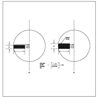
10.1.4.1.3 For Type S Pitot Tube combinations with complete Probe assemblies, the calibration point should be located at or near the center of the duct; however, insertion of a Probe sheath into a small duct may cause significant cross-sectional area interference and blockage and yield incorrect coefficient values (Reference 9 in Section 17.0). Therefore, to minimize the blockage effect, the calibration point may be a few inches off-center if necessary. The actual blockage effect will be negligible when the theoretical blockage, as determined by a projected area model of the Probe sheath, is 2 percent or less of the duct cross-sectional area for assemblies without external sheaths (Figure 2-10a), and 3 percent or less for assemblies with external sheaths (Figure 2-10b).
10.1.4.2 For those Probe assemblies in which pitot tube-nozzle interference is a factor (i.e., those in which the pitot-nozzle separation distance fails to meet the specifications illustrated in Figure 2-7A), the value of Cp(s) depends upon the amount of free space between the tube and nozzle and, therefore, is a function of nozzle size. In these instances, separate calibrations shall be performed with each of the commonly used nozzle sizes in place. Note that the single-velocity calibration technique is acceptable for this purpose, even though the larger nozzle sizes (>0.635 cm or 1/4 in.) are not ordinarily used for isokinetic sampling at velocities around 910 m/min (3,000 ft/min), which is the calibration velocity. Note also that it is not necessary to draw an isokinetic sample during calibration (see Reference 19 in Section 17.0).
10.1.4.3 For a Probe assembly constructed such that its pitot tube is always used in the same orientation, only one side of the pitot tube need be calibrated (the side which will face the flow). The pitot tube must still meet the alignment specifications of Figure 2-2 or 2-3, however, and must have an average deviation (F) value of 0.01 or less (see Section 10.1.4.4).
10.1.5 Field Use and Recalibration
10.1.5.1 Field Use
10.1.5.1.1 When a Type S Pitot Tube (isolated or in an assembly) is used in the field, the appropriate coefficient value (whether assigned or obtained by calibration) shall be used to perform velocity calculations. For calibrated Type S Pitot Tubes, the A-side coefficient shall be used when the A-side of the tube faces the flow, and the B-side coefficient shall be used when the B-side faces the flow. Alternatively, the arithmetic average of the A and B side coefficient values may be used, irrespective of which side faces the flow.
10.1.5.1.2 When a Probe assembly is used to sample a small duct, 30.5 to 91.4 cm (12 to 36 in.) in diameter, the Probe sheath sometimes blocks a significant part of the duct cross-section, causing a reduction in the effective value of Cp(s). Consult Reference 9 (see Section 17.0) for details. Conventional pitot-sampling Probe assemblies are not recommended for use in ducts having inside diameters smaller than 30.5 cm (12 in.) (see Reference 16 in Section 17.0).
10.1.5.2 Recalibration
10.1.5.2.1 Isolated pitot Tubes. After each field use, the pitot tube shall be carefully reexamined in top, side, and end views. If the pitot face openings are still aligned within the specifications illustrated in Figure 2-2 and 2-3, it can be assumed that the baseline coefficient of the pitot tube has not changed. If, however, the tube has been damaged to the extent that it no longer meets the specifications of Figure 2-2 and 2-3, the damage shall either be repaired to restore proper alignment of the face openings, or the tube shall be discarded.
10.1.5.2.2 Type S Pitot Tube. After each field use, check the face opening alignment of the pitot tube, as in Section 10.1.5.2.1. Also, remeasure the intercomponent spacings of the assembly. If the intercomponent spacings have not changed and the face opening alignment is acceptable, it can be assumed that the coefficient of the assembly has not changed. If the face opening alignment is no longer within the specifications of Figure 2-2 and Figure 2-3, either repair the damage or replace the pitot tube (calibrating the new assembly, if necessary). If the intercomponent spacings have changed, restore the original spacings, or recalibrate the assembly.
10.2 Standard Pitot Tube (if applicable)
If a standard pitot tube is used for the velocity traverse, the tube shall be constructed according to the criteria of Section 6.7 and shall be assigned a baseline coefficient value of 0.99. If the standard pitot tube is used as part of an assembly, the tube shall be in an interference-free arrangement (subject to the approval of the Administrator).
10.3 Temperature Sensors
10.3.1 After each field use, calibrate dial thermometers, liquid-filled bulb thermometers, thermocouple potentiometer systems, and other sensors at a temperature within 10 percent of the average absolute stack temperature. For temperatures up to 405C (761F), use an ASTM mercury in-glass reference thermometer, or equivalent, as a reference. Alternatively, either a reference thermocouple and potentiometer (calibrated against NIST standards) or thermometric fixed points (e.g., ice bath and boiling water, corrected for barometric pressure) may be used. For temperatures above 405C (761F), use a reference thermocouple-potentiometer system calibrated against NIST standards or an alternative reference, subject to the approval of the Administrator.
10.3.2 The temperature data recorded in the field shall be considered valid. If, during calibration, the absolute temperature measured with the sensor being calibrated and the reference sensor agree within 1.5 percent, the temperature data taken in the field shall be considered valid. Otherwise, the pollutant emission test shall either be considered invalid or adjustments (if appropriate) of the test results shall be made, subject to the approval of the Administrator.
10.4 barometer
Calibrate the barometer used against a mercury barometer.
11.0 Analytical Procedure
Sample collection and analysis are concurrent for this method (see Section 8.0).
12.0 Data Analysis and Calculations
Carry out calculations, retaining at least one extra significant figure beyond that of the acquired data. Round off figures after final calculation.
12.1 Nomenclature
A = Cross-sectional area of stack, m2 (ft2).
Bws = Water vapor in the gas stream [from Method 4 (reference method) or Method 5], proportion by volume.
Cp = pitot tube coefficient, dimensionless.
Cp(s) = Type S Pitot Tube coefficient, dimensionless.
Cp(std) = standard pitot tube coefficient; use 0.99 if the coefficient is unknown and the tube is designed according to the criteria of Sections 6.7.1 to 6.7.5 of this method.
De = Equivalent diameter.
K = 0.127 mm H2O (metric units) = 0.005 in. H2O (English units).
Kp = Velocity equation constant.
L = Length.
Md = Molecular weight of stack gas, dry basis (see Section 8.6), g/g-mole (lb/lb-mole).
Ms = Molecular weight of stack gas, wet basis, g/g-mole (lb/lb-mole).
n = Total number of traverse points.
Pbar = Barometric pressure at measurement site, mm Hg (in. Hg).
Pg = Stack static pressure, mm Hg (in. Hg).
Ps = Absolute stack pressure (Pbar + Pg), mm Hg (in. Hg),
Pstd = Standard absolute pressure, 760 mm Hg (29.92 in. Hg).
Qsd = Dry volumetric stack gas flow rate corrected to standard conditions, dscm/hr (dscf/hr).
T = Sensitivity factor for differential pressure gauges .
Ts = Stack temperature, C (F).
Ts(abs) = Absolute stack temperature, K (R).
= 273 + Ts for metric units,
= 460 + Ts for English units.
Tstd = Standard absolute temperature, 293 K (528 R).
vs = Average stack gas velocity, m/sec (ft/sec).
W = Width.
Δp = Velocity head of stack gas, mm H2O (in. H20).
Δpi = Individual velocity head reading at traverse point "i", mm (in.) H2O.
Δpstd = Velocity head measured by the standard pitot tube , cm (in.) H2O.
Δps = Velocity head measured by the Type S Pitot Tube, cm (in.) H2O.
3600 = Conversion Factor, sec/hr.
18.0 = Molecular weight of water, g/g-mole (lb/lbmole).
12.2 Calculate T as follows:
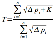 Eq. 2-1
12.3 Calculate De as follows:
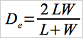 Eq. 2-2
12.4 calibration of Type S Pitot Tube
12.4.1 For each of the six pairs of Δp readings (i.e., three from side A and three from side B) obtained in Section 10.1.3, calculate the value of the Type S Pitot Tube coefficient according to Equation 2-3:
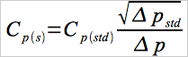 Eq. 2-3
12.4.2 Calculate Cp(A), the mean A-side coefficient, and Cp(B), the mean B-side coefficient. Calculate the difference between these two average values.
12.4.3 Calculate the deviation of each of the three A-side values of Cp(s) from Cp(A), and the deviation of each of the three B-side values of Cp(s) from Cp(B), using Equation 2-4:
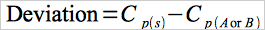 Eq. 2-4
12.4.4 Calculate F, the average deviation from the mean, for both the A and B sides of the pitot tube. Use Equation 2-5:
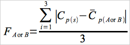 Eq. 2-5
12.5 Molecular Weight of Stack Gas
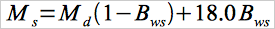 Eq. 2-6
12.6 Average Stack Gas Velocity
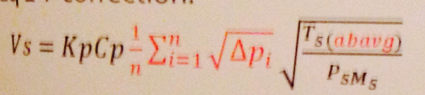 Eq. 2-7
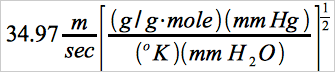 Metric
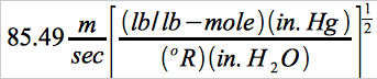 English
12.7 Average Stack Gas Dry Volumetric flow rate
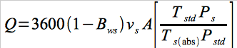 Eq. 2-8
13.0 Method Performance [Reserved]
14.0 Pollution Prevention [Reserved]
15.0 Waste Management [Reserved]
16.0 References
1. Mark, L.S. Mechanical Engineers' Handbook. New York. McGraw-Hill Book Co., Inc. 1951.
2. Perry, J.H., ed. Chemical Engineers' Handbook. New York. McGraw-Hill Book Co., Inc. 1960.
3. Shigehara, R.T., W.F. Todd, and W.S. Smith. Significance of Errors in Stack Sampling Measurements. U.S. Environmental Protection Agency, Research Triangle Park, N.C. (Presented at the Annual Meeting of the Air Pollution Control Association, St. Louis, MO., June 14-19, 1970).
4. Standard Method for Sampling Stacks for Particulate Matter. In: 1971 Book of ASTM Standards, Part 23. Philadelphia, PA. 1971. ASTM Designation D 2928-71.
5. Vennard, J.K. Elementary Fluid Mechanics. New York. John Wiley and Sons, Inc. 1947.
6. Fluid meters - Their Theory and Application. American Society of Mechanical Engineers, New York, N.Y. 1959.
7. ASHRAE Handbook of Fundamentals. 1972. p. 208.
8. Annual Book of ASTM Standards, Part 26. 1974. p. 648.
9. Vollaro, R.F. Guidelines for Type S Pitot Tube Calibration. U.S. Environmental Protection Agency, Research Triangle Park, N.C. (Presented at 1st Annual Meeting, Source Evaluation Society, Dayton, OH, September 18, 1975.)
10. Vollaro, R.F. A Type S Pitot Tube Calibration Study. U.S. Environmental Protection Agency, Emission Measurement Branch, Research Triangle Park, N.C. July 1974.
11. Vollaro, R.F. The Effects of Impact Opening Misalignment on the Value of the Type S Pitot Tube Coefficient. U.S. Environmental Protection Agency, Emission Measurement Branch, Research Triangle Park, NC. October 1976.
12. Vollaro, R.F. Establishment of a Baseline Coefficient Value for Properly Constructed Type S Pitot Tubes. U.S. Environmental Protection Agency, Emission Measurement Branch, Research Triangle Park, NC. November 1976.
13. Vollaro, R.F. An Evaluation of Single-Velocity Calibration Technique as a Means of Determining Type S Pitot Tube Coefficients. U.S. Environmental Protection Agency, Emission Measurement Branch, Research Triangle Park, NC. August 1975.
14. Vollaro, R.F. The Use of Type S Pitot Tubes for the Measurement of Low Velocities. U.S. Environmental Protection Agency, Emission Measurement Branch, Research Triangle Park, NC. November 1976.
15. Smith, Marvin L. Velocity calibration of EPA Type Source Sampling Probe. United Technologies Corporation, Pratt and Whitney Aircraft Division, East Hartford, CT. 1975.
16. Vollaro, R.F. Recommended Procedure for Sample Traverses in Ducts Smaller than 12 Inches in Diameter. U.S. Environmental Protection Agency, Emission Measurement Branch, Research Triangle Park, NC. November 1976.
17. Ower, E. and R.C. Pankhurst. The Measurement of Air flow, 4th Ed. London, Pergamon Press. 1966.
18. Vollaro, R.F. A Survey of Commercially Available Instrumentation for the Measurement of Low-Range Gas Velocities. U.S. Environmental Protection Agency, Emission Measurement Branch, Research Triangle Park, NC. November 1976. (Unpublished Paper).
19. Gnyp, A.W., et al. An Experimental Investigation of the Effect of Pitot Tube-Sampling Probe Configurations on the Magnitude of the S Type pitot Tube Coefficient for Commercially Available Source Sampling Probes. Prepared by the University of Windsor for the Ministry of the Environment, Toronto, Canada. February 1975.
17.0 Tables, Diagrams, flowcharts, and Validation Data
Figure 2-1. Type S Pitot Tube Manometer Assembly.
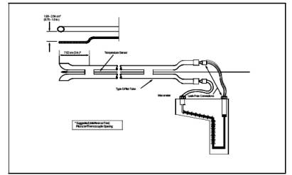
Figure 2-2. Properly Constructed Type S Pitot Tube.

Figure 2-3. Types of face-opening misalignments that can result from field use or improper construction of Type S Pitot Tubes.
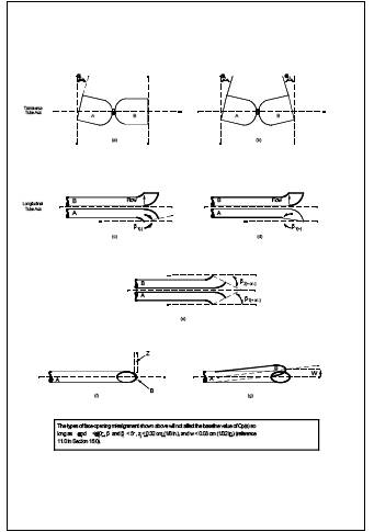
Figure 2-4. Proper temperature sensor placement to prevent interference; Dt between 0.48 and 0.95 cm (3/16 and 3/8 in).
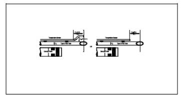
Figure 2-5. standard pitot tube design specifications.
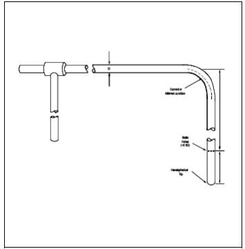
Figure 2-6. Velocity traverse data.
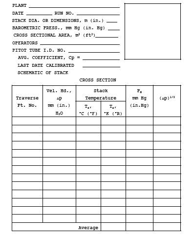
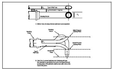
Figure 2-8. Minimum pitot-sample Probe separation needed to prevent interference; Dt between 0.48 and 0.95 cm (3/16 and 3/8 in).
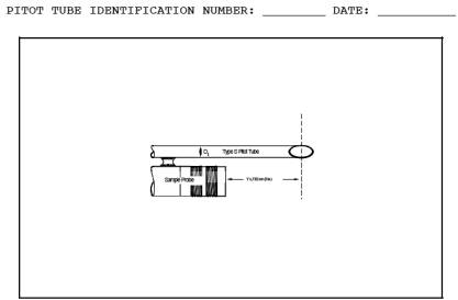
Figure 2-9. pitot tube calibration data.
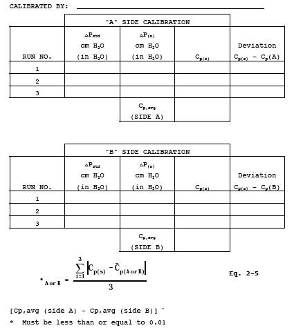
Figure 2-10. Projected-area models for typical Type S Pitot Tube.
RELATED LINKS
USA EPA Webpage for EPA Method 2
Comparison of This Page with EPA Method 2 online.
- Analytical
- Ion Chromatography
- Gas Chromatography
- Gravimetrics
- Ash Resistivity
- Inks/Coatings
- Scrubber Stoichiometry
- Titrations
- Mercury Sorbent Trap
- Engineering
- Express Products
- Rental Instruments
- MET80 Mercury Monitor
- Continuous Emission Monitors
- Gas Sampling Equipment
- Mobile Power Supply
Our Resources
- Technical Resources