- Home
- Careers
- Contact
- About
-
Who we are and what we do. -
Press releases, announcements, and notable corporate information. -
We are looking for a few A people. -
We have over 40 years of innovation to create value for our customers. -
We aim to be the highest value provider of every product and service we offer. -
An easy guide to Probe fundamentals.
-
- Services
-
In additional to the analytical results we normally include an expert analysts summary.
We use our decades of experience to help you better understand your data. -
CleanAir can insures that the project goals and testing are objectives are met.
-
We can ship what you need today. It will work. You get a company of experts when you rent from CleanAir. - Thermal Performance
-
- Rental
-
Our factory reconditioning experts work to make old as good as new. -
CleanAir can provide the services required to care of your emissions measurement or power measurement instruments, no matter the age, model or manufacturer.
-
We deliver rental, emergency, or supplemental instruments and onsite services quickly, with minimal operational interruptions .
-
- Products
Featured Product

UL Listed Mobile Temporary Power
Look professional. Don't risk a OSHA fine, or worse causing your customer to get an OSHA or MSHA fine by using an unsafe mobile power distribution system. The CleanAir Temporary Power cart is UL listed! Read more... -
Reference
-
Overviews of products and services -
Learn about our companies and business -
Detailed technical information about the functioning of our products -
Guides and instructions on proper installation and service -
Guides and instructions on proper installation and service -
Drawings, configuration, materials, and limits useful for the planning and layout.
-
CleanAir's reference of video content -
Publications addressing an issue or topic
-
- Site Map
 Express
 FTIR
FTIR Mercury
 Emission Sampling Equipment
 Instrument Rental
EPA Methods List with Links
US EPA Method 107 - Determination Of Vinyl Chloride Content Of In- Process Wastewater Samples, And Vinyl Chloride Content Of Polyvinyl Chloride Resin, Slurry, Wet Cake, And Latex Samples
NOTE: Performance of this method should not be attempted by persons unfamiliar with the operation of a gas chromatograph (GC) nor by those who are unfamiliar with source sampling, because knowledge beyond the scope of this presentation is required. This method does not include all of the specifications (e.g., equipment and supplies) and procedures (e.g., sampling and analytical) essential to its performance. Some material is incorporated by reference from other methods in this part. Therefore, to obtain reliable results, persons using this method should have a thorough knowledge of at least the following additional test methods: Method 106.
1.0 Scope and Application.
1.1 Analytes.
| Analyte | CAS No. | Sensitivity |
| Vinyl Chloride (CH2:CHCl) | 75-01-4 | Dependent upon analytical equipment |
1.2 Applicability.
This method is applicable for the determination of the vinyl chloride monomer (VCM) content of in-process wastewater samples, and the residual vinyl chloride monomer (RCVM) content of polyvinyl chloride (PVC) resins, wet, cake, slurry, and latex samples. It cannot be used for polymer in fused forms, such as sheet or cubes.
This method is not acceptable where methods from Section 304 (h) of the Clean Water Act, 33 U.S.C. 1251 et seq. (the Federal Water Pollution Control Amendments of 1972 as amended by the Clean Water Act of 1977) are required.
1.3 Data Quality Objectives.
Adherence to the requirements of this method will enhance the quality of the data obtained from air pollutant sampling methods.
2.0 Summary of Method.
2.1 The basis for this method relates to the vapor equilibrium that is established at a constant known temperature in a closed system between RVCM, PVC resin, water, and air. The RVCM in a PVC resin will equilibrate rapidly in a closed vessel, provided that the temperature of the PVC resin is maintained above the glass transition temperature of that specific resin.
2.2 A sample of PVC or in-process wastewater is collected in a vial or bottle and is conditioned. The headspace in the vial or bottle is then analyzed for vinyl chloride using gas chromatography with a flame ionization detector.
3.0 Definitions. [Reserved]
4.0 Interferences.
4.1 The chromatograph columns and the corresponding
operating parameters herein described normally provide an adequate resolution of vinyl chloride; however, resolution interferences may be encountered on some sources. Therefore, the chromatograph operator shall select the column and operating parameters best suited to his particular analysis requirements, subject to the approval of the Administrator. Approval is automatic provided that confirming data are produced through an adequate supplemental analytical technique, such as analysis with a different column or GC/mass spectroscopy, and that these data are made available for review by the Administrator.
5.0 Safety.
5.1 Disclaimer.
This method may involve hazardous materials, operations, and equipment. This test method may not address all of the safety problems associated with its use. It is the responsibility of the user of this test method to establish appropriate safety and health practices and determine the applicability of regulatory limitations prior to performing this test method.
5.2 Toxic Analyte.
Care must be exercised to prevent exposure of sampling personnel to vinyl chloride, which is a carcinogen. Do not release vinyl chloride to the laboratory atmosphere during preparation of standards. Venting or purging with VCM/air mixtures must be held to a minimum.
When they are required, the vapor must be routed to outside air. Vinyl chloride, even at low ppm levels, must never be vented inside the laboratory. After vials have been analyzed, the gas must be vented prior to removal of the vial from the instrument turntable. Vials must be vented through a hypodermic needle connected to an activated charcoal tube to prevent release of vinyl chloride into the laboratory atmosphere. The charcoal must be replaced prior to vinyl chloride breakthrough.
6.0 Equipment and Supplies.
6.1 Sample Collection.
The following equipment is required:
6.1.1 glass bottles. 60-ml (2-oz) capacity, with wax-lined screw-on tops, for PVC samples.
6.1.2 glass Vials. Headspace vials, with Teflon-faced butyl rubber sealing discs, for water samples.
6.1.3 Adhesive Tape. To prevent loosening of bottle tops.
6.2 Sample Recovery.
The following equipment is required:
6.2.1 glass Vials. Headspace vials, with butyl rubber septa and aluminum caps. Silicone rubber is not acceptable.
6.2.2 Analytical Balance. Capable of determining sample weight within an accuracy of ±1 percent.
6.2.3 Vial Sealer. To seal headspace vials.
6.2.4 Syringe. 100-ml capacity.
6.3 Analysis.
The following equipment is required:
6.3.1 Headspace Sampler and Chromatograph. Capable of sampling and analyzing a constant amount of headspace gas from a sealed vial, while maintaining that vial at a temperature of 90 °C ± 0.5 °C (194 °F ± 0.9 °F). The chromatograph shall be equipped with a flame ionization detector (FID). Perkin-Elmer Corporation Models F-40, F-42, F-45, HS-6, and HS-100, and Hewlett-Packard Corporation Model 19395A have been found satisfactory. Chromatograph backflush capability may be required.
6.3.2 Chromatographic Columns. Stainless steel 1 m by 3.2 mm and 2 m by 3.2 mm, both containing 50/80-mesh Porapak Q. Other columns may be used provided that the precision and accuracy of the analysis of vinyl chloride standards are not impaired and information confirming that there is adequate resolution of the vinyl chloride peak are available for review. (Adequate resolution is defined as an area overlap of not more than 10 percent of the vinyl chloride peak by an interferant peak. Calculation of area overlap is explained in Procedure 1 of appendix C to this part: "Determination of Adequate Chromatographic Peak Resolution.") Two 1.83 m columns, each containing 1 percent Carbowax 1500 on Carbopak B, have been found satisfactory for samples containing acetaldehyde.
6.3.3 temperature sensor. Range 0 to 100 °C (32 to 212 °F) accurate to 0.1°C.
6.3.4 Integrator-Recorder. To record chromatograms.
6.3.5 barometer. Accurate to 1 mm Hg.
6.3.6 Regulators. For required gas cylinders.
6.3.7 Headspace Vial Pre-Pressurizer. Nitrogen pressurized hypodermic needle inside protective shield.
7.0 Reagents and Standards.
7.1 Analysis.
Same as Method 106, Section 7.1, with the addition of the following:
7.1.1 Water. Interference-free.
7.2 calibration.
The following items are required for calibration:
7.2.1 Cylinder Standards (4).
Gas mixture standards (50-, 500-, 2000- and 4000-ppm vinyl chloride in nitrogen cylinders). Cylinder standards may be used directly to prepare a chromatograph calibration curve as described in Section 10.3, if the following conditions are met: (a) The manufacturer certifies the gas composition with an accuracy of ±3 percent or better (see Section 7.2.1.1). (b) The manufacturer recommends a maximum shelf life over which the gas concentration does not change by greater than ±5 percent from the certified value. (c) The manufacturer affixes the date of gas cylinder preparation, certified vinyl chloride concentration, and recommended maximum shelf life to the cylinder before shipment to the buyer.
7.2.1.1 Cylinder Standards Certification.
The manufacturer shall certify the concentration of vinyl chloride in nitrogen in each cylinder by (a) directly analyzing each cylinder and (b) calibrating the analytical procedure on the day of cylinder analysis. To calibrate the analytical procedure, the manufacturer shall use, as a minimum, a 3-point calibration curve. It is recommended that the manufacturer maintain (1) a high-concentration calibration standard (between 4000 and 8000 ppm) to prepare the calibration curve by an appropriate dilution technique and (2) a low-concentration calibration standard (between 50 and 500 ppm) to verify the dilution technique used. If the difference between the apparent concentration read from the calibration curve and the true concentration assigned to the low-concentration calibration standard exceeds 5 percent of the true concentration, the manufacturer shall determine the source of error and correct it, then repeat the 3-point calibration.
7.2.1.2 Verification of Manufacturer's calibration Standards.
Before using, the manufacturer shall verify each calibration standard by (a) comparing it to gas mixtures prepared (with 99 mole percent vinyl chloride) in accordance with the procedure described in Section 10.1 of Method 106 or by (b) calibrating it against vinyl chloride cylinder Standard Reference Materials (SRMs) prepared by the National Institute of Standards and Technology, if such SRMs are available. The agreement between the initially determined concentration value and the verification concentration value must be within 5 percent. The manufacturer must reverify all calibration standards on a time interval consistent with the shelf life of the cylinder standards sold.
8.0 Sample Collection, Preservation, Storage, and Transport.
8.1 Sample Collection.
8.1.1 PVC Sampling.
Allow the resin or slurry to flow from a tap on the tank or silo until the tap line has been well purged. Extend and fill a 60-ml sample bottle under the tap, and immediately tighten a cap on the bottle. Wrap adhesive tape around the cap and bottle to prevent the cap from loosening. Place an identifying label on each bottle, and record the date, time, and sample location both on the bottles and in a log book.
8.1.2 Water Sampling.
At the sampling location fill the vials bubble-free to overflowing so that a convex meniscus forms at the top. The excess water is displaced as the sealing disc is carefully placed, with the Teflon side down, on the opening of the vial. Place the aluminum seal over the disc and the neck of the vial, and crimp into place. Affix an identifying label on the bottle, and record the date, time, and sample location both on the vials and in a log book.
8.2 Sample Storage.
All samples must be analyzed within 24 hours of collection, and must be refrigerated during this period.
9.0 Quality Control.
| Section | Quality Control Measure | Effect |
| 10.3 | Chromatograph calibration | Ensure precision and accuracy of chromatograph |
10.0 Calibration and Standardization.
NOTE: Maintain a laboratory log of all calibrations.
10.1 Preparation of Standards.
calibration standards are prepared as follows: Place 100μl or about two equal drops of distilled water in the sample vial, then fill the vial with the VCM/nitrogen standard, rapidly seat the septum, and seal with the aluminum cap. Use a c-in. stainless steel line from the cylinder to the vial. Do not use rubber or Tygon tubing. The sample line from the cylinder must be purged (into a properly vented hood) for several minutes prior to filling the vials. After purging, reduce the flow rate to between 500 and 1000 cc/min. Place end of tubing into vial (near bottom). Position a septum on top of the vial, pressing it against the c-in. filling tube to minimize the size of the vent opening. This is necessary to minimize mixing air with the standard in the vial. Each vial is to be purged with standard for 90 seconds, during which time the filling tube is gradually slid to the top of the vial. After the 90 seconds, the tube is removed with the septum, simultaneously sealing the vial. Practice will be necessary to develop good technique. Rubber gloves should be worn during the above operations. The sealed vial must then be pressurized for 60 seconds using the vial prepressurizer. Test the vial for leakage by placing a drop of water on the septum at the needle hole. Prepressurization of standards is not required unless samples have been prepressurized.
10.2 Analyzer calibration.
calibration is to be performed each 8-hour period the chromatograph is used. Alternatively, calibration with duplicate 50-, 500-, 2,000-, and 4,000-ppm standards (hereafter described as a four-point calibration) may be performed on a monthly basis, provided that a calibration confirmation test consisting of duplicate analyses of an appropriate standard is performed once per plant shift, or once per chromatograph carrousel operation (if the chromatograph operation is less frequent than once per shift). The criterion for acceptance of each calibration confirmation test is that both analyses of 500-ppm standards [2,000-ppm standards if dispersion resin (excluding latex resin) samples are being analyzed] must be within 5 percent of the most recent four-point calibration curve. If this criterion is not met, then a complete four-point calibration must be performed before sample analyses can proceed.
10.3 Preparation of Chromatograph calibration Curve.
Prepare two vials each of 50-, 500-, 2,000-, and 4,000-ppm standards. Run the calibration samples in exactly the same manner as regular samples. Plot As, the integrator area counts for each standard sample, versus Cc, the concentration of vinyl chloride in each standard sample. Draw a straight line through the points derived by the least squares method.
11.0 Analytical Procedure.
11.1 Preparation of equipment.
Install the chromatographic column and condition overnight at 160 °C (320 °F). In the first operation, Porapak columns must be purged for 1 hour at 230 °C (450 °F). Do not connect the exit end of the column to the detector while conditioning. Hydrogen and air to the detector must be turned off while the column is disconnected.
11.2 flow Rate Adjustments.
Adjust flow rates as follows:
11.2.1. Nitrogen Carrier Gas.
Set regulator on cylinder to read 50 psig. Set regulator on chromatograph to produce a flow rate of 30.0 cc/min. Accurately measure the flow rate at the exit end of the column using the soap film flowmeter and a stopwatch, with the oven and column at the analysis temperature. After the instrument program advances to the "B" (backflush) mode, adjust the nitrogen pressure regulator to exactly balance the nitrogen flow rate at the detector as was obtained in the "A" mode.
11.2.2. Vial Prepressurizer Nitrogen.
11.2.2.1 After the nitrogen carrier is set, solve the following equation and adjust the pressure on the vial prepressurizer accordingly.
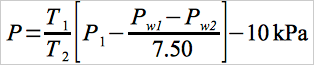 Eq. 107-1
where:
| T1 | = | Ambient temperature, °K (°R). |
| T2 | = | Conditioning bath temperature, °K (°R). |
| P1 | = | Gas chromatograph absolute dosing pressure (analysis mode), kPa. |
| Pw1 | = | Water vapor pressure 525.8 mm Hg @ 90 °C. |
| Pw2 | = | Water vapor pressure 19.8 mm Hg @ 22 °C. |
| 7.50 | = | mm Hg per k Pa. |
| 10 kPa | = | Factor to adjust the prepressurized pressure to slightly less than the dosing pressure. |
11.2.2.2 Because of gauge errors, the apparatus may over-pressurize the vial. If the vial pressure is at or higher than the dosing pressure, an audible double injection will occur. If the vial pressure is too low, errors will occur on resin samples because of inadequate time for head-space gas equilibrium. This condition can be avoided by running several standard gas samples at various pressures around the calculated pressure, and then selecting the highest pressure that does not produce a double injection. All samples and standards must be pressurized for 60 seconds using the vial prepressurizer. The vial is then placed into the 90 °C conditioning bath and tested for leakage by placing a drop of water on the septum at the needle hole. A clean, burr-free needle is mandatory.
11.2.3. Burner Air Supply.
Set regulator on cylinder to read 50 psig. Set regulator on chromatograph to supply air to burner at a rate between 250 and 300 cc/min. Check with bubble flowmeter.
11.2.4. Hydrogen Supply.
Set regulator on cylinder to read 30 psig. Set regulator on chromatograph to supply approximately 35 ± 5 cc/min. Optimize hydrogen flow to yield the most sensitive detector response without extinguishing the flame. Check flow with bubble meter and record this flow.
11.3 temperature Adjustments.
Set temperatures as follows:
11.3.1. oven (chromatograph column), 140 °C (280 °F). 11.3.2. Dosing Line, 150 °C (300 °F).
11.3.3. Injection Block, 170 °C (340 °F).
11.3.4. Sample Chamber, Water temperature, 90 °C ± 1.0 °C (194 °F ± 1.8 °F).
11.4 Ignition of Flame Ionization Detector.
Ignite the detector according to the manufacturer's instructions.
11.5 Amplifier Balance.
Balance the amplifier according to the manufacturer's instructions.
11.6 Programming the Chromatograph.
Program the chromatograph as follows:
11.6.1. I ) Dosing or Injection Time. The normal setting is 2 seconds.
11.6.2. A ) Analysis Time. The normal setting is approximately 70 percent of the VCM retention time. When this timer terminates, the programmer initiates backflushing of the first column.
11.6.3. B ) Backflushing Time. The normal setting is double the analysis time.
11.6.4. W ) Stabilization Time. The normal setting is 0.5 min to 1.0 min.
11.6.5. X ) Number of Analyses Per Sample. The normal setting is one.
11.7. Sample Treatment.
All samples must be recovered and analyzed within 24 hours after collection.
11.7.1 Resin Samples.
The weight of the resin used must be between 0.1 and 4.5 grams. An exact weight must be obtained (within ±1 percent) for each sample. In the case of suspension resins, a volumetric cup can be prepared for holding the required amount of sample. When the cup is used, open the sample bottle, and add the cup volume of resin to the tared sample vial (tared, including septum and aluminum cap). Obtain the exact sample weight, add 100 ml or about two equal drops of water, and immediately seal the vial. Report this value on the data sheet; it is required for calculation of RVCM. In the case of dispersion resins, the cup cannot be used. Weigh the sample in an aluminum dish, transfer the sample to the tared vial, and accurately weigh it in the vial. After prepressurization of the samples, condition them for a minimum of 1 hour in the 90 °C (190 °F) bath. Do not exceed 5 hours. Prepressurization is not required if the sample weight, as analyzed, does not exceed 0.2 gram. It is also not required if solution of the prepressurization equation yields an absolute prepressurization value that is within 30 percent of the atmospheric pressure.
NOTE: Some aluminum vial caps have a center section that must be removed prior to placing into sample tray. If the cap is not removed, the injection needle will be damaged.
11.7.2 Suspension Resin Slurry and Wet Cake Samples.
Decant the water from a wet cake sample, and turn the sample bottle upside down onto a paper towel. Wait for the water to drain, place approximately 0.2 to 4.0 grams of the wet cake sample in a tared vial (tared, including septum and aluminum cap) and seal immediately. Then determine the sample weight (1 percent). All samples weighing over 0.2 gram, must be prepressurized prior to conditioning for 1 hour at 90 °C (190 °F), except as noted in Section 11.7.1. A sample of wet cake is used to determine total solids (TS). This is required for calculating the RVCM.
11.7.3 Dispersion Resin Slurry and Geon Latex Samples.
The materials should not be filtered. Sample must be thoroughly mixed. Using a tared vial (tared, including septum and aluminum cap) add approximately eight drops (0.25 to 0.35 g) of slurry or latex using a medicine dropper. This should be done immediately after mixing. Seal the vial as soon as possible. Determine sample weight (1 percent). Condition the vial for 1 hour at 90 °C (190 °F) in the analyzer bath. Determine the TS on the slurry sample (Section 11.10).
11.7.4 In-process Wastewater Samples.
Using a tared vial (tared, including septum and aluminum cap) quickly add approximately 1 cc of water using a medicine dropper. Seal the vial as soon as possible. Determine sample weight (1 percent). Condition the vial for 1 hour at 90 °C (190 °F) in the analyzer bath.
11.8 Preparation of Sample Turntable.
11.8.1 Before placing any sample into turntable, be certain that the center section of the aluminum cap has been removed. The numbered sample vials should be placed in the corresponding numbered positions in the turntable. Insert samples in the following order:
11.8.1.1 Positions 1 and 2. Old 2000-ppm standards for conditioning. These are necessary only after the analyzer has not been used for 24 hours or longer.
11.8.1.2 Position 3. 50-ppm standard, freshly prepared.
11.8.1.3 Position 4. 500-ppm standard, freshly prepared.
11.8.1.4 Position 5. 2000-ppm standard, freshly prepared.
11.8.1.5 Position 6. 4000-ppm standard, freshly prepared.
11.8.1.6 Position 7. Sample No. 7 (This is the first sample of the day, but is given as 7 to be consistent with the turntable and the integrator printout.)
11.8.2 After all samples have been positioned, insert the second set of 50-, 500-, 2000-, and 4000-ppm standards. Samples, including standards, must be conditioned in the bath of 90 °C (190 °F) for a minimum of one hour and a maximum of five hours.
11.9 Start Chromatograph Program.
When all samples, including standards, have been conditioned at 90 °C (190 °F) for at least one hour, start the analysis program according to the manufacturer's instructions. These instructions must be carefully followed when starting and stopping a program to prevent damage to the dosing assembly.
11.10 Determination of Total Solids.
For wet cake, slurry, resin solution, and PVC latex samples, determine TS for each sample by accurately weighing approximately 3 to 4 grams of sample in an aluminum pan before and after placing in a draft oven [105 to 110 °C (221 to 230 °F)]. Samples must be dried to constant weight. After first weighing, return the pan to the oven for a short period of time, and then reweigh to verify complete dryness. The TS are then calculated as the final sample weight divided by initial sample weight.
12.0 Calculations and Data Analysis.
12.1 Nomenclature.
| As | = | Chromatogram area counts of vinyl chloride for the sample, area counts. |
| As | = | Chromatogram area counts of vinyl chloride for the sample. |
| Cc | = | Concentration of vinyl chloride in the standard sample, ppm. |
| Kp | = | Henry's Law Constant for VCM in PVC 90 °C, 6.52 10-6 g/g/mm Hg. |
| Kw | = | Henry's Law Constant for VCM in water 90 °C, 7 10-7 g/g/mm Hg. |
| Mv | = | Molecular weight of VCM, 62.5 g/mole. |
| m | = | Sample weight, g. |
| Pa | = | Ambient atmospheric pressure, mm Hg. |
| R | = | Gas constant, (62360 3 ml) (mm Hg)/(mole)(°K). |
| Rf | = | Response factor in area counts per ppm VCM. |
| Rs | = | Response factor, area counts/ppm. |
| Tl | = | Ambient laboratory temperature, °K. |
| TS | = | Total solids expressed as a decimal fraction. |
| T2 | = | Equilibrium temperature, °K. |
| Vg | = | Volume of vapor phase, ml. |
| Vv | = | Vial volume, 3 ml. |
| 1.36 | = | Density of PVC at 90 °C, g/3 ml. |
| 0.9653 | = | Density of water at 90 °C, g/3 ml. |
12.2 Response Factor.
If the calibration curve described in Section 10.3 passes through zero, an average response factor, Rf, may be used to facilitate computation of vinyl chloride sample concentrations.
12.2.1 To compute Rf, first compute a response factor, Rs, for each sample as follows:
 Eq. 107-2
12.2.2 Sum the individual response factors, and calculate Rf. If the calibration curve does not pass through zero, use the calibration curve to determine each sample concentration.
12.3 Residual Vinyl Chloride Monomer Concentration, (Crvc) or Vinyl Chloride Monomer Concentration. Calculate Crvc in ppm or mg/kg as follows:
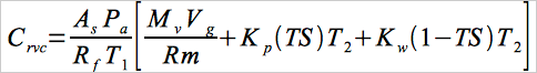 Eq. 107-3
NOTE: Results calculated using these equations represent concentration based on the total sample. To obtain results based on dry PVC content, divide by TS.
13.0 Method Performance.
13.1 Range and Sensitivity.
The lower limit of detection of vinyl chloride will vary according to the sampling and chromatographic system. The system should be capable of producing a measurement for a 50-ppm vinyl chloride standard that is at least 10 times the standard deviation of the system background noise level.
13.2 An interlaboratory comparison between seven laboratories of three resin samples, each split into three parts, yielded a standard deviation of 2.63 percent for a sample with a mean of 2.09 ppm, 4.16 percent for a sample with a mean of 1.66 ppm, and 5.29 percent for a sample with a mean of 62.66 ppm.
14.0 Pollution Prevention. [Reserved]
15.0 Waste Management. [Reserved]
16.0 References.
1. B.F. Goodrich, Residual Vinyl Chloride Monomer Content of Polyvinyl Chloride Resins, Latex, Wet Cake, Slurry and Water Samples. B.F. Goodrich Chemical Group Standard Test Procedure No. 1005-E. B.F. Goodrich Technical Center, Avon Lake, Ohio. October 8, 1979.
2. Berens, A.R. The Diffusion of Vinyl Chloride in Polyvinyl Chloride. ACS)Division of Polymer Chemistry, Polymer Preprints 15 (2):197. 1974.
3. Berens, A.R. The Diffusion of Vinyl Chloride in Polyvinyl Chloride. ACS)Division of Polymer Chemistry, Polymer Preprints 15 (2):203. 1974.
4. Berens, A.R., et. al. Analysis for Vinyl Chloride in PVC Powders by Head)Space Gas Chromatography. Journal of Applied Polymer Science. 19:3169-3172. 1975.
5. Mansfield, R.A. The Evaluation of Henry's Law Constant (Kp) and Water Enhancement in the Perkin-Elmer Multifract F-40 Gas Chromatograph. B.F. Goodrich. Avon Lake, Ohio. February 10, 1978.
17.0 Tables, Diagrams, flowcharts, and Validation Data. [Reserved]
- Analytical
- Ion Chromatography
- Gas Chromatography
- Gravimetrics
- Ash Resistivity
- Inks/Coatings
- Scrubber Stoichiometry
- Titrations
- Mercury Sorbent Trap
- Engineering
- Express Products
- Rental Instruments
- MET80 Mercury Monitor
- Continuous Emission Monitors
- Gas Sampling Equipment
- Mobile Power Supply
Our Resources
- Technical Resources