- Home
- Careers
- Contact
- About
-
Who we are and what we do. -
Press releases, announcements, and notable corporate information. -
We are looking for a few A people. -
We have over 40 years of innovation to create value for our customers. -
We aim to be the highest value provider of every product and service we offer. -
An easy guide to Probe fundamentals.
-
- Services
-
In additional to the analytical results we normally include an expert analysts summary.
We use our decades of experience to help you better understand your data. -
CleanAir can insures that the project goals and testing are objectives are met.
-
We can ship what you need today. It will work. You get a company of experts when you rent from CleanAir. - Thermal Performance
-
- Rental
-
Our factory reconditioning experts work to make old as good as new. -
CleanAir can provide the services required to care of your emissions measurement or power measurement instruments, no matter the age, model or manufacturer.
-
We deliver rental, emergency, or supplemental instruments and onsite services quickly, with minimal operational interruptions .
-
- Products
Featured Product

UL Listed Mobile Temporary Power
Look professional. Don't risk a OSHA fine, or worse causing your customer to get an OSHA or MSHA fine by using an unsafe mobile power distribution system. The CleanAir Temporary Power cart is UL listed! Read more... -
Reference
-
Overviews of products and services -
Learn about our companies and business -
Detailed technical information about the functioning of our products -
Guides and instructions on proper installation and service -
Guides and instructions on proper installation and service -
Drawings, configuration, materials, and limits useful for the planning and layout.
-
CleanAir's reference of video content -
Publications addressing an issue or topic
-
- Site Map
 Express
 FTIR
FTIR Mercury
 Emission Sampling Equipment
 Instrument Rental
EPA Methods List with Links
US EPA Method 106 - Determination Of Vinyl Chloride Emissions From Stationary Sources
Content [ show/hide ].1.0 Scope and Application.
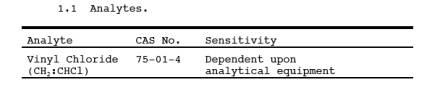
1.1 Analytes.
1.2 Applicability.
This method is applicable for the determination of vinyl chloride emissions from ethylene dichloride, vinyl chloride, and polyvinyl chloride manufacturing processes. This method does not measure vinyl chloride contained in particulate matter.
1.3 Data Quality Objectives.
Adherence to the requirements of this method will enhance the quality of the data obtained from air pollutant sampling methods.
2.0 Summary of Method.
2.1 An integrated bag sample of stack gas containing vinyl chloride is subjected to GC analysis using a flame ionization detector (FID).
3.0 Definitions. [Reserved]
4.0 Interferences.
4.1 Resolution interferences of vinyl chloride may be encountered on some sources. Therefore, the chromatograph operator should select the column and operating parameters best suited to the particular analysis requirements. The selection made is subject to approval of the Administrator. Approval is automatic, provided that confirming data are produced through an adequate supplemental analytical technique, and that the data are available for review by the Administrator. An example of this would be analysis with a different column or GC/mass spectroscopy.
5.0 Safety.
5.1 Disclaimer. This method may involve hazardous materials, operations, and equipment. This test method may not address all of the safety problems associated with its use. It is the responsibility of the user of this test method to establish appropriate safety and health practices and determine the applicability of regulatory limitations prior to performing this test method.
5.2 Toxic Analyte. Care must be exercised to prevent exposure of sampling personnel to vinyl chloride, which is a carcinogen.
6.0 Equipment and Supplies.
6.1 Sample Collection.
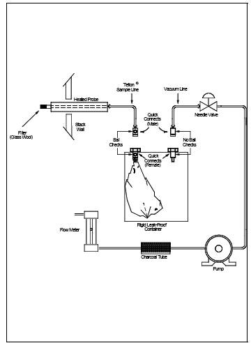
(See Figure 106-1) The sampling train consists of the following components:
6.1.1 Probe. Stainless steel, borosilicate glass, Teflon tubing (as stack temperature permits), or equivalent, equipped with a glass wool plug to remove particulate matter.
6.1.2 Sample Lines. Teflon, 6.4-mm outside diameter, of sufficient length to connect Probe to bag. Use a new unused piece for each series of bag samples that constitutes an emission test, and discard upon completion of the test.
6.1.3 Quick Connects. Stainless steel, male (2) and female (2), with ball checks (one pair without), located as shown in Figure 106-1.
6.1.4 . 50-to 100-liter capacity, to contain sample. Aluminized Mylar bags may be used if the samples are analyzed within 24 hours of collection.
6.1.5 Bag Containers. Rigid leak-proof containers for sample bags, with covering to protect contents from sunlight.
6.1.6 Needle Valve. To adjust sample flow rates.
6.1.7 pump. Leak-free, with minimum of 2-liter/min capacity.
6.1.8 Charcoal Tube. To prevent admission of vinyl chloride and other organics to the atmosphere in the vicinity of samplers.
6.1.9 flowmeter. For observing sampling flow rate; capable of measuring a flow range from 0.10 to 1.00 liter/min.
6.1.10 Connecting tubing. Teflon, 6.4-mm outside diameter, to assemble sampling train (Figure 106-1).
6.1.11 tubing Fittings and Connectors. Teflon or stainless steel, to assemble sampling training.
6.2 Sample Recovery.
Teflon tubing, 6.4-mm outside diameter, to connect bag to GC sample loop. Use a new unused piece for each series of bag samples that constitutes an emission test, and discard upon conclusion of analysis of those bags.
6.3 Analysis.
The following equipment is required:
6.3.1 Gas Chromatograph. With FID potentiometric strip chart recorder and 1.0 to 5.0-ml heated sampling loop in automatic sample valve. The chromatographic system shall be capable of producing a response to 0.1-ppmv vinyl chloride that is at least as great as the average noise level. (Response is measured from the average value of the base line to the maximum of the wave form, while standard operating conditions are in use.)
6.3.2 Chromatographic Columns. Columns as listed below. Other columns may be used provided that the precision and accuracy of the analysis of vinyl chloride standards are not impaired and that information is available for review confirming that there is adequate resolution of vinyl chloride peak. (Adequate resolution is defined as an area overlap of not more than 10 percent of the vinyl chloride peak by an interferent peak. Calculation of area overlap is explained in Procedure 1 of appendix C to this part: "Determination of Adequate Chromatographic Peak Resolution.")
6.3.2.1 Column A. Stainless steel, 2.0 m by 3.2 mm, containing 80/100-mesh Chromasorb 102.
6.3.2.2 Column B. Stainless steel, 2.0 m by 3.2 mm, containing 20 percent GE SF-96 on 60/ip-mesh Chromasorb P AW; or stainless steel, 1.0 m by 3.2 mm containing 80/100-mesh Porapak T. Column B is required as a secondary column if acetaldehyde is present. If used, column B is placed after column A. The combined columns should be operated at 120 C (250 F).
6.3.3 Rate meters (2). Rotameter , or equivalent, 100-ml/min capacity, with flow control valves.
6.3.4 Gas Regulators. For required gas cylinders.
6.3.5 tenperature sensor. Accurate to ±1 C (± 2 F), to measure temperature of heated sample loop at time of sample injection.
6.3.6 barometer. Accurate to ±5 mm Hg, to measure atmospheric pressure around GC during sample analysis.
6.3.7 pump. Leak-free, with minimum of 100-ml/min capacity.
6.3.8 Recorder. Strip chart type, optionally equipped with either disc or electronic integrator.
6.3.9 Planimeter. Optional, in place of disc or electronic integrator on recorder, to measure chromatograph peak areas.
6.4 calibration and Standardization.
6.4.1 tubing. Teflon, 6.4-mm outside diameter, separate pieces marked for each calibration concentration.
NOTE: The following items are required only if the optional standard gas preparation procedures (Section 10.1) are followed.
6.4.2 Tedlar Bags. Sixteen-inch-square size, with valve; separate bag marked for each calibration concentration.
6.4.3 Syringes. 0.5-ml and 50-l, gas tight, individually calibrated to dispense gaseous vinyl chloride.
6.4.4 console meter with temperature and Pressure gauges. Singer Model DTM-115 with 802 index, or equivalent, to meter nitrogen in preparation of standard gas mixtures, calibrated at the flow rate used to prepare standards.
7.0 Reagents and Standards.
7.1 Analysis.
The following reagents are required for analysis.
7.1.1 Helium or Nitrogen. Purity 99.9995 percent or greater, for chromatographic carrier gas.
7.1.2 Hydrogen. Purity 99.9995 percent or greater.
7.1.3 Oxygen or Air. Either oxygen (purity 99.99 percent or greater) or air (less than 0.1 ppmv total hydrocarbon content), as required by detector.
7.2 calibration.
Use one of the following options: either Sections 7.2.1 and 7.2.2, or Section 7.2.3.
7.2.1 Vinyl Chloride.
Pure vinyl chloride gas certified by the manufacturer to contain a minimum of 99.9 percent vinyl chloride. If the gas manufacturer maintains a bulk cylinder supply of 99.9+ percent vinyl chloride, the certification analysis may have been performed on this supply, rather than on each gas cylinder prepared from this bulk supply. The date of gas cylinder preparation and the certified analysis must have been affixed to the cylinder before shipment from the gas manufacturer to the buyer.
7.2.2 Nitrogen.
Same as described in Section 7.1.1.
7.2.3 Cylinder Standards.
Gas mixture standards (50-,10-, and 5 ppmv vinyl chloride) in nitrogen cylinders may be used to directly prepare a chromatograph calibration curve as described in Section 10.3 if the following conditions are met: (a) The manufacturer certifies the gas composition with an accuracy of ±3 percent or better. (b) The manufacturer recommends a maximum shelf life over which the gas concentration does not change by greater than ± 5 percent from the certified value. (c) The manufacturer affixes the date of gas cylinder preparation, certified vinyl chloride concentration, and recommended maximum shelf to the cylinder before shipment to the buyer.
7.2.3.1 Cylinder Standards Certification. The manufacturer shall certify the concentration of vinyl chloride in nitrogen in each cylinder by (a) directly analyzing each cylinder and (b) calibrating his analytical procedure on the day of cylinder analysis. To calibrate his analytical procedure, the manufacturer shall use as a minimum, a three point calibration curve. It is recommended that the manufacturer maintain (1) a high concentration calibration standard (between 50 and 100 ppmv) to prepare his calibration curve by an appropriate dilution technique and (2) a low-concentration calibration standard (between 5 and 10 ppmv) to verify the dilution technique used. If the difference between the apparent concentration read from the calibration curve and the true concentration assigned to the low-concentration calibration standard exceeds 5 percent of the true concentration, the manufacturer shall determine the source of error and correct it, then repeat the three-point calibration.
7.2.3.2 Verification of Manufacturer's calibration Standards. Before using a standard, the manufacturer shall verify each calibration standard (a) by comparing it to gas mixtures prepared (with 99 mole percent vinyl chloride) in accordance with the procedure described in Section 7.2.1 or (b) calibrating it against vinyl chloride cylinder Standard Reference Materials (SRM's) prepared by the National Institute of Standards and Technology, if such SRM's are available. The agreement between the initially determined concentration value and the verification concentration value must be ±5 percent. The manufacturer must re-verify all calibration standards on a time interval consistent with the shelf life of the cylinder standards sold.
7.2.4 Audit Cylinder Standards.
7.2.4.1 Gas mixture standards with concentrations known only to the person supervising the analysis of samples. The concentrations of the audit cylinders should be: one low-concentration cylinder in the range of 5 to 20 ppmv vinyl chloride and one high-concentration cylinder in the range of 20 to 50 ppmv. When available, obtain audit samples from the appropriate EPA Regional Office or from the responsible enforcement authority.
NOTE: The responsible enforcement agency should be notified at least 30 days prior to the test date to allow sufficient time for sample delivery.
7.2.4.2 Alternatively, audit cylinders obtained from a commercial gas manufacturer may be used provided: (a) the gas meets the conditions described in Section 7.2.3, (b) the gas manufacturer certifies the audit cylinder as described in Section 7.2.3.1, and (c) the gas manufacturer obtains an independent analysis of the audit cylinders to verify this analysis. Independent analysis is defined here to mean analysis performed by an individual different than the individual who performs the gas manufacturer's analysis, while using calibration standards and analysis equipment different from those used for the gas manufacturer's analysis. Verification is complete and acceptable when the independent analysis concentration is within 5 percent of the gas manufacturer's concentration.
8.0 Sample Collection, Preservation, Storage, and Transport.
NOTE: Performance of this method should not be attempted by persons unfamiliar with the operation of a gas chromatograph (GC) nor by those who are unfamiliar with source sampling, because knowledge beyond the scope of this presentation is required.
8.1 Bag Leak-Check.
The following leak-check procedure is recommended, but not required, prior to sample collection. The post-test leak-check procedure is mandatory. Connect a water manometer and pressurize the bag to 5 to 10 cm H2O (2 to 4 in. H2O). Allow to stand for 10 min. Any displacement in the water manometer indicates a leak. Also, check the rigid container for leaks in this manner.
NOTE: An alternative leak-check method is to pressurize the bag to 5 to 10 cm H2O and allow it to stand overnight. A deflated bag indicates a leak. For each sample bag in its rigid container, place a rotameter in line between the bag and the pump inlet. Evacuate the bag. Failure of the rotameter to register zero flow when the bag appears to be empty indicates a leak.
8.2 Sample Collection.
Assemble the sample train as shown in Figure 106-1. Join the quick connects as illustrated, and determine that all connection between the bag and the Probe are tight. Place the end of the Probe at the centroid of the stack and start the pump with the needle valve adjusted to yield a flow that will fill over 50 percent of bag volume in the specific sample period. After allowing sufficient time to purge the line several times, change the vacuum line from the container to the bag and evacuate the bag until the rotameter indicates no flow. Then reposition the sample and vacuum lines and begin the actual sampling, keeping the rate proportional to the stack velocity. At all times, direct the gas exiting the rotameter away from sampling personnel. At the end of the sample period, shut off the pump, disconnect the sample line from the bag, and disconnect the vacuum line from the bag container. Protect the bag container from sunlight.
8.3 Sample Storage.
Keep the sample bags out of direct sunlight. When at all possible, analysis is to be performed within 24 hours, but in no case in excess of 72 hours of sample collection. Aluminized Mylar bag samples must be analyzed within 24 hours.
8.4 Post-test Bag Leak-Check.
Subsequent to recovery and analysis of the sample, leak-check the sample bag according to the procedure outlined in Section 8.1.
9.0 Quality Control.
9.1 Miscellaneous Quality Control.
9.2 Immediately after the preparation of the calibration curve and prior to the sample analyses, perform the analysis audit described in href="https://www.arb.ca.gov/bluebook/bb05/40cfr/40cfrpart61appc.htm">Appendix C, Procedure 2: "Procedure for Field Auditing GC Analysis."
10.0 Calibration and Standardization.
NOTE: Maintain a laboratory log of all calibrations.
10.1 Preparation of Vinyl Chloride Standard Gas Mixtures.
(Optional Procedure-delete if cylinder standards are used.) Evacuate a 16-inch square Tedlar Bag that has passed a leak-check (described in Section 8.1) and meter in 5.0 liters of nitrogen. While the bag is filling, use the 0.5-ml syringe to inject 250 l of 99.9+ percent vinyl chloride gas through the wall of the bag. Upon withdrawing the syringe, immediately cover the resulting hole with a piece of adhesive tape. The bag now contains a vinyl chloride concentration of 50 ppmv. In a like manner use the 50 l syringe to prepare gas mixtures having 10- and 5-ppmv vinyl chloride concentrations. Place each bag on a smooth surface and alternately depress opposite sides of the bag 50 times to further mix the gases. These gas mixture standards may be used for 10 days from the date of preparation, after which time new gas mixtures must be prepared. (Caution: Contamination may be a problem when a bag is reused if the new gas mixture standard is a lower concentration than the previous gas mixture standard.)
10.2 Determination of Vinyl Chloride Retention Time.
(This section can be performed simultaneously with Section 10.3.) Establish chromatograph conditions identical with those in Section 11.3. Determine proper attenuator position. Flush the sampling loop with helium or nitrogen and activate the sample valve. Record the injection time, sample loop temperature, column temperature, carrier gas flow rate, chart speed, and attenuator setting. Record peaks and detector responses that occur in the absence of vinyl chloride. Maintain conditions with the equipment plumbing arranged identically to Section 11.2, and flush the sample loop for 30 seconds at the rate of 100 ml/min with one of the vinyl chloride calibration mixtures. Then activate the sample valve. Record the injection time. Select the peak that corresponds to vinyl chloride. Measure the distance on the chart from the injection time to the time at which the peak maximum occurs. This quantity divided by the chart speed is defined as the retention time. Since other organics may be present in the sample, positive identification of the vinyl chloride peak must be made.
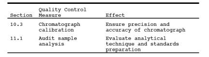
10.3 Preparation of Chromatograph calibration Curve.
Make a GC measurement of each gas mixture standard (described in Section 7.2.3 or 10.1) using conditions identical to those listed in Sections 11.2 and 11.3. Flush the sampling loop for 30 seconds at the rate of 100 ml/min with one of the standard mixtures, and activate the sample valve. Record the concentration of vinyl chloride injected (Cc), attenuator setting, chart speed, peak area, sample loop temperature, column temperature, carrier gas flow rate, and retention time. Record the barometric pressure. Calculate Ac, the peak area multiplied by the attenuator setting. Repeat until two consecutive injection areas are within 5 percent, then plot the average of those two values versus Cc. When the other standard gas mixtures have been similarly analyzed and plotted, draw a straight line through the points derived by the least squares method. Perform calibration daily, or before and after the analysis of each emission test set of bag samples, whichever is more frequent. For each group of sample analyses, use the average of the two calibration curves which bracket that group to determine the respective sample concentrations. If the two calibration curves differ by more than 5 percent from their mean value, then report the final results by both calibration curves.
11.0 Analytical Procedure.
11.1 Audit Sample Analysis.
Immediately after the preparation of the calibration curve and prior to the sample analyses, perform the analysis audit described in Procedure 2 of appendix C to this part: "Procedure for Field Auditing GC Analysis."
11.2 Sample Recovery.
With a new piece of Teflon tubing identified for that bag, connect a bag inlet valve to the gas chromatograph sample valve. Switch the valve to receive gas from the bag through the sample loop. Arrange the equipment so the sample gas passes from the sample valve to 100-ml/min rotameter with flow control valve followed by a charcoal tube and a 1-in. H2O pressure gauge. Maintain the sample flow either by a vacuum pump or container pressurization if the collection bag remains in the rigid container. After sample loop purging is ceased, allow the pressure gauge to return to zero before activating the gas sampling valve.
11.3 Analysis.
11.3.1 Set the column temperature to 100 C (210 F) and the detector temperature to 150 C (300 F). When optimum hydrogen and oxygen (or air) flow rates have been determined, verify and maintain these flow rates during all chromatography operations. Using helium or nitrogen as the carrier gas, establish a flow rate in the range consistent with the manufacturer's requirements for satisfactory detector operation. A flow rate of approximately 40 ml/min should produce adequate separations. Observe the base line periodically and determine that the noise level has stabilized and that base line drift has ceased. Purge the sample loop for 30 seconds at the rate of 100 ml/min, shut off flow, allow the sample loop pressure to reach atmospheric pressure as indicated by the H2O manometer, then activate the sample valve. Record the injection time (the position of the pen on the chart at the time of sample injection), sample number, sample loop temperature, column temperature, carrier gas flow rate, chart speed, and attenuator setting. Record the barometric pressure. From the chart, note the peak having the retention time corresponding to vinyl chloride as determined in Section 10.2. Measure the vinyl chloride peak area, Am, by use of a disc integrator, electronic integrator, or a planimeter. Measure and record the peak heights, Hm. Record Am and retention time. Repeat the injection at least two times or until two consecutive values for the total area of the vinyl chloride peak agree within 5 percent of their average. Use the average value for these two total areas to compute the bag concentration.
11.3.2 Compare the ratio of Hm to Am for the vinyl chloride sample with the same ratio for the standard peak that is closest in height. If these ratios differ by more than 10 percent, the vinyl chloride peak may not be pure (possibly acetaldehyde is present) and the secondary column should be employed (see Section 6.3.2.2).
11.4 Determination of Bag Water Vapor Content.
Measure the ambient temperature and barometric pressure near the bag. From a water saturation vapor pressure table, determine and record the water vapor content of the bag, Bwb, as a decimal figure. (Assume the relative humidity to be 100 percent unless a lesser value is known.)
12.0 Calculations and Data Analysis.
12.1 Nomenclature.
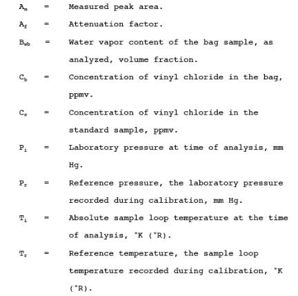
12.2 Sample Peak Area. Determine the sample peak area, Ac, as follows:

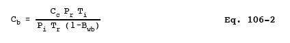
12.3 Vinyl Chloride Concentration. From the calibration curves prepared in Section 10.3, determine the average concentration value of vinyl chloride, Cc, that corresponds to Ac, the sample peak area. Calculate the concentration of vinyl chloride in the bag, C>b, as follows:
13.0 Method Performance.
13.1 Analytical Range. This method is designed for the 0.1 to 50 parts per million by volume (ppmv) range. However, common gas chromatograph (GC) instruments are capable of detecting 0.02 ppmv vinyl chloride. With proper calibration, the upper limit may be extended as needed.
14.0 Pollution Prevention. [Reserved]
15.0 Waste Management. [Reserved]
16.0 References.
1. Brown D.W., E.W. Loy, and M.H. Stephenson. Vinyl Chloride Monitoring Near the B. F. Goodrich Chemical Company in Louisville, KY. Region IV, U.S. Environmental Protection Agency, Surveillance and Analysis Division, Athens, GA. June 24, 1974.
2. G.D. Clayton and Associates. Evaluation of a Collection and Analytical Procedure for Vinyl Chloride in Air. U.S. Environmental Protection Agency, Research Triangle Park, N.C. EPA Contract No. 68-02-1408, Task Order No. 2, EPA Report No. 75-VCL-1. December 13, 1974.
3. Midwest Research Institute. Standardization of Stationary Source Emission Method for Vinyl Chloride. U.S. Environmental Protection Agency, Research Triangle Park, N.C. Publication No. EPA-600/4-77-026. May 1977.
4. Scheil, G. and M.C. Sharp. Collaborative Testing of EPA Method 106 (Vinyl Chloride) that Will Provide for a Standardized Stationary Source Emission Measurement Method. U.S. Environmental Protection Agency, Research Triangle Park, N.C. Publication No. EPA 600/4-78-058. October 1978.
17.0 Tables, Diagrams flowcharts, and Validation Data.
Figure 106-1. Integrated-bag sampling train.
- Analytical
- Ion Chromatography
- Gas Chromatography
- Gravimetrics
- Ash Resistivity
- Inks/Coatings
- Scrubber Stoichiometry
- Titrations
- Mercury Sorbent Trap
- Engineering
- Express Products
- Rental Instruments
- MET80 Mercury Monitor
- Continuous Emission Monitors
- Gas Sampling Equipment
- Mobile Power Supply
Our Resources
- Technical Resources