- Home
- Careers
- Contact
- About
-
Who we are and what we do. -
Press releases, announcements, and notable corporate information. -
We are looking for a few A people. -
We have over 40 years of innovation to create value for our customers. -
We aim to be the highest value provider of every product and service we offer. -
An easy guide to Probe fundamentals.
-
- Services
-
In additional to the analytical results we normally include an expert analysts summary.
We use our decades of experience to help you better understand your data. -
CleanAir can insures that the project goals and testing are objectives are met.
-
We can ship what you need today. It will work. You get a company of experts when you rent from CleanAir. - Thermal Performance
-
- Rental
-
Our factory reconditioning experts work to make old as good as new. -
CleanAir can provide the services required to care of your emissions measurement or power measurement instruments, no matter the age, model or manufacturer.
-
We deliver rental, emergency, or supplemental instruments and onsite services quickly, with minimal operational interruptions .
-
- Products
Featured Product

UL Listed Mobile Temporary Power
Look professional. Don't risk a OSHA fine, or worse causing your customer to get an OSHA or MSHA fine by using an unsafe mobile power distribution system. The CleanAir Temporary Power cart is UL listed! Read more... -
Reference
-
Overviews of products and services -
Learn about our companies and business -
Detailed technical information about the functioning of our products -
Guides and instructions on proper installation and service -
Guides and instructions on proper installation and service -
Drawings, configuration, materials, and limits useful for the planning and layout.
-
CleanAir's reference of video content -
Publications addressing an issue or topic
-
- Site Map
 Express
 FTIR
FTIR Mercury
 Emission Sampling Equipment
 Instrument Rental
EPA Methods List with Links
US EPA Method 5I - Determination of Low Level Particulate Matter Emissions From Stationary Sources
Note: This method does not include all of the specifications (e.g., equipment and supplies) and procedures (e.g., sampling and analytical) essential to its performance. Certain information is contained in other EPA procedures found in this part. Therefore, to obtain reliable results, persons using this method should have experience with and a thorough knowledge of the following Methods: Methods 1, 2, 3, 4 and 5.
Necessary equipment for performing Method 5
1. Scope and Application.
1.1 Analyte.
Particulate matter (PM). No CAS number assigned.
1.2 Applicability.
This method is applicable for the determination of low level particulate matter (PM) emissions from stationary sources. The method is most effective for total PM catches of 50 mg or less. This method was initially developed for performing correlation of manual PM measurements to PM continuous emission monitoring systems (CEMS), however it is also useful for other low particulate concentration applications.
1.3 Data Quality Objectives.
Adherence to the requirements of this method will enhance the quality of the data obtained from air pollutant sampling methods. Method 5I requires the use of paired trains. Acceptance criteria for the identification of data quality outliers from the paired trains are provided in Section 12.2 of this Method.
2. Summary of Method.
2.1. Description.
The system setup and operation is essentially identical to Method 5. Particulate is withdrawn isokinetically from the source and collected on a 47 mm glass fiber filter maintained at a temperature of 120 ± 14C (248 ± 25F). The PM mass is determined by gravimetric analysis after the removal of uncombined water. Specific measures in this procedure designed to improve system performance at low particulate levels include: 1. Improved sample handling procedures 2 Light weight sample filter assembly 3. Use of low residue grade acetone Accuracy is improved through the minimization of systemic errors associated with sample handling and weighing procedures. High purity reagents, all glass, grease free, sample train components, and light weight filter assemblies and beakers, each contribute to the overall objective of improved precision and accuracy at low particulate concentrations.
2.2 Paired trains.
This method must be performed using a paired train configuration. These trains may be operated as co-located trains (to trains operating collecting from one port) or as simultaneous trains (separate trains operating from different ports at the same time). Procedures for calculating precision of the paired trains are provided in Section 12.
2.3 Detection Limit.
a. Typical detection limit for manual particulate testing is 0.5 mg. This mass is also cited as the accepted weight variability limit in determination of ‘‘constant weight’’ as cited in Section 8.1.2 of this Method. EPA has performed studies to provide guidance on minimum PM catch. The minimum detection limit (MDL) is the minimum concentration or amount of an analyte that can be determined with a specified degree of confidence to be different from zero. We have defined the minimum or target catch as a concentration or amount sufficiently larger than the MDL to ensure that the results are reliable and repeatable. The particulate matter catch is the product of the average particulate matter concentration on a mass per volume basis and the volume of gas collected by the sample train. The tester can generally control the volume of gas collected by increasing the sampling time or to a lesser extent by increasing the rate at which sample is collected. If the tester has a reasonable estimate of the PM concentration from the source, the tester can ensure that the target catch is collected by sampling the appropriate gas volume.
b. However, if the source has a very low particulate matter concentration in the stack, the volume of gas sampled may need to be very large which leads to unacceptably long sampling times. When determining compliance with an emission limit, EPA guidance has been that the tester does not always have to collect the target catch. Instead, we have suggested that the tester sample enough stack gas, that if the source were exactly at the level of the emission standard, the sample catch would equal the target catch. Thus, if at the end of the test the catch were smaller than the target, we could still conclude that the source is in compliance though we might not know the exact emission level. This volume of gas becomes a target volume that can be translated into a target sampling time by assuming an average sampling rate. Because the MDL forms the basis for our guidance on target sampling times, EPA has conducted a systematic laboratory study to define what is the MDL for Method 5 and determined the Method to have a calculated practical quantitation limit (PQL) of 3 mg of PM and an MDL of 1 mg.
c. Based on these results, the EPA has concluded that for PM testing, the target catch must be no less than 3 mg. Those sample catches between 1 mg and 3 mg are between the detection limit and the limit of quantitation. If a tester uses the target catch to estimate a target sampling time that results in sample catches that are less than 3 mg, you should not automatically reject the results. If the tester calculated the target sampling time as described above by assuming that the source was at the level of the emission limit, the results would still be valid for determining that the source was in compliance. For purposes other than determining compliance, results should be divided into two categories—those that fall between 3 mg and 1 mg and those that are below 1 mg. A sample catch between 1 and 3 mg may be used for such purposes as calculating emission rates with the understanding that the resulting emission rates can have a high degree of uncertainty. Results of less than 1 mg should not be used for calculating emission rates or pollutant concentrations.
d. When collecting small catches such as 3 mg, bias becomes an important issue. Source testers must use extreme caution to reach the PQL of 3 mg by assuring that sampling Probes are very clean (perhaps confirmed by low blank weights) before use in the field. They should also use low tare weight sample containers, and establish a well-controlled balance room to weigh the samples.
3. Definitions.
3.1 Light Weight filter Housing.
A smaller housing that allows the entire filtering system to be weighed before and after sample collection. (See. 6.1.3)
3.2 Paired train.
Sample systems trains may be operated as co-located trains (two sample Probes attached to each other in the same port) or as simultaneous trains (two separate trains operating from different ports at the same time).
4. Interferences.
a. There are numerous potential interferents that may be encountered during performance of Method 5I sampling and analyses. This Method should be considered more sensitive to the normal interferents typically encountered during particulate testing because of the low level concentrations of the flue gas stream being sampled.
b. Care must be taken to minimize field contamination, especially to the filter housing since the entire unit is weighed (not just the filter media). Care must also be taken to ensure that no sample is lost during the sampling process (such as during port changes, removal of the filter assemblies from the Probes, etc.).
c. Balance room conditions are a source of concern for analysis of the low level samples. Relative humidity, ambient temperatures variations, air draft, vibrations and even barometric pressure can affect consistent reproducible measurements of the sample media. Ideally, the same analyst who performs the tare weights should perform the final weights to minimize the effects of procedural differences specific to the analysts.
d. Attention must also be provided to weighing artifacts caused by electrostatic charges which may have to be discharged or neutralized prior to sample analysis. Static charge can affect consistent and reliable gravimetric readings in low humidity environments. Method 5I recommends a relative humidity of less than 50 percent in the weighing room environment used for sample analyses. However, lower humidity may be encountered or required to address sample precision problems. Low humidity conditions can increase the effects of static charge.
e. Other interferences associated with typical Method 5 testing (sulfates, acid gases, etc.) are also applicable to Method 5I.
5. Safety.
Disclaimer. This method may involve hazardous materials, operations, and equipment. This test method may not address all of the safety concerns associated with its use. It is the responsibility of the user to establish appropriate safety and health practices and to determine the applicability and observe all regulatory limitations before using this method.
6.0 Equipment and Supplies.
6.1 Sample Collection equipment and supplies.
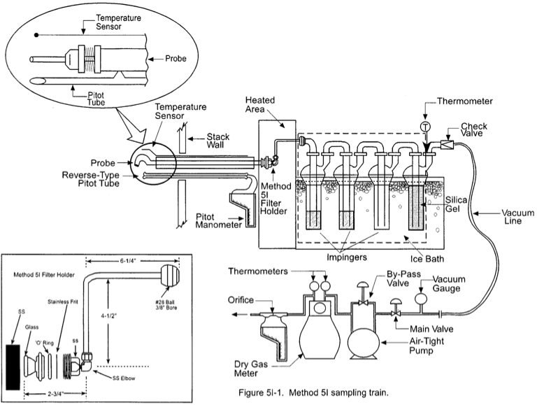
The sample train is nearly identical in configuration to the train depicted in Figure 5-1 of Method 5. The primary difference in the sample trains is the lightweight Method 5I filter assembly that attaches directly to the exit to the Probe. Other exceptions and additions specific to Method 5I include:
6.1.1 Probe probe nozzle.
Same as Method 5, with the exception that it must be constructed of borosilicate or quartz glass tubing.
6.1.2 Probe liner.
Same as Method 5, with the exception that it must be constructed of borosilicate or quartz glass tubing.
6.1.3 filter Holder.
The filter holder is constructed of borosilicate or quartz glass front cover designed to hold a 47-mm glass fiber filter, with a wafer thin stainless steel (SS) filter support, a silicone rubber or Viton O-ring, and Teflon tape seal. This holder design will provide a positive seal against leakage from the outside or around the filter. The filter holder assembly fits into a SS filter holder and attaches directly to the outlet of the Probe. The tare weight of the filter, borosilicate or quartz glass holder, SS filter support, O-ring and Teflon tape seal generally will not exceed approximately 35 grams. The filter holder is designed to use a 47-mm glass fiber filter meeting the quality criteria in of Method 5. These units are commercially available from several source testing equipment vendors. Once the filter holder has been assembled, desiccated and tared, protect it from external sources of contamination by covering the front socket with a ground glass plug. Secure the plug with an impinger clamp or other item that will ensure a leak-free fitting.
6.2 sample recovery equipment and supplies.
Same as Method 5, with the following exceptions:
6.2.1 Probe-Liner and Probe-probe nozzle Brushes.
Teflon or nylon bristle brushes with stainless steel wire handles, should be used to clean the Probe. The Probe brush must have extensions (at least as long as the Probe) of Teflon, nylon or similarly inert material. The brushes must be properly sized and shaped for brushing out the Probe liner and probe nozzle.
6.2.2 Wash Bottles.
Two Teflon wash bottles are recommended however, polyethylene wash bottles may be used at the option of the tester. Acetone should not be stored in polyethylene bottles for longer than one month.
6.2.3 filter Assembly Transport.
A system should be employed to minimize contamination of the filter assemblies during transport to and from the field test location. A carrying case or packet with clean compartments of sufficient size to accommodate each filter assembly can be used. This system should have an air tight seal to further minimize contamination during transport to and from the field.
6.3 Analysis equipment and supplies.
Same as Method 5, with the following exception:
6.3.1 Lightweight Beaker Liner.
Teflon or other lightweight beaker liners are used for the analysis of the Probe and probe nozzle rinses. These light weight liners are used in place of the borosilicate glass beakers typically used for the Method 5 weighings in order to improve sample analytical precision.
6.3.2 Anti-static Treatment.
Commercially available gaseous anti-static rinses are recommended for low humidity situations that contribute to static charge problems.
7. Reagents and Standards.
7.1 Sampling Reagents.
The reagents used in sampling are the same as Method 5 with the following exceptions:
7.1.1 filters.
The quality specifications for the filters are identical to those cited for Method 5. The only difference is the filter diameter of 47 millimeters.
7.1.2 Stopcock Grease.
Stopcock grease cannot be used with this sampling train. We recommend that the sampling train be assembled with glass joints containing O-ring seals or screw-on connectors, or similar.
7.1.3 Acetone.
Low residue type acetone, ≤0.001 percent residue, purchased in glass bottles is used for the recovery of particulate matter from the Probe and probe nozzle. Acetone from metal containers generally has a high residue blank and should not be used. Sometimes, suppliers transfer acetone to glass bottles from metal containers; thus, acetone blanks must be run prior to field use and only acetone with low blank values (≤0.001 percent residue, as specified by the manufacturer) must be used. Acetone blank correction is not allowed for this method; therefore, it is critical that high purity reagents be purchased and verified prior to use.
7.1.4 Gloves.
Disposable, powder-free, latex surgical gloves, or their equivalent are used at all times when handling the filter housings or performing sample recovery.
7.2 Standards.
There are no applicable standards or audit samples commercially available for Method 5I analyses.
8. Sample Collection, Preservation, Storage, and Transport.
8.1 Pretest Preparation.
Same as Method 5 with several exceptions specific to filter assembly and weighing.
8.1.1 filter Assembly.
Uniquely identify each filter support before loading filters into the holder assembly. This can be done with an engraving tool or a permanent marker. Use powder free latex surgical gloves whenever handling the filter holder assemblies. Place the O-ring on the back of the filter housing in the O-ring groove. Place a 47 mm glass fiber filter on the O-ring with the face down. Place a stainless steel filter holder against the back of the filter. Carefully wrap 5 mm (1⁄4 inch) wide Teflon’’ tape one timearound the outside of the filter holder overlapping the stainless steel filter support by approximately 2.5 mm (1⁄8 inch). Gently brush the Teflon tape down on the back of the stainless steel filter support. Store the filter assemblies in their transport case until time for weighing or field use.
8.1.2 filter Weighing Procedures.
a. Desiccate the entire filter holder assemblies at 20 ± 5.6C (68 ± 10F) and ambient pressure for at least 24 hours. Weigh at intervals of at least 6 hours to a constant weight, i.e., 0.5 mg change from previous weighing. Record the results to the nearest 0.1 mg. During each weighing, the filter holder assemblies must not be exposed to the laboratory atmosphere for a period greater than 2 minutes and a relative humidity above 50 percent. Lower relative humidity may be required in order to improve analytical precision. However, low humidity conditions increase static charge to the sample media.
b. Alternatively (unless otherwise specified by the Administrator), the filters holder assemblies may be oven dried at 105C (220F) for a minimum of 2 hours, desiccated for 2 hours, and weighed. The procedure used for the tare weigh must also be used for the final weight determination.
c. Experience has shown that weighing uncertainties are not only related to the balance performance but to the entire weighing procedure. Therefore, before performing any measurement, establish and follow standard operating procedures, taking into account the sampling equipment and filters to be used.
8.2 Preliminary Determinations.
Select the sampling site, traverse points, Probe probe nozzle, and Probe length as specified in Method 5.
8.3 Preparation of Sampling train.
Same as Method 5, Section 8.3, with the following exception: During preparation and assembly of the sampling train, keep all openings where contamination can occur covered until justbefore assembly or until sampling is about to begin. Using gloves, place a labeled (identified) and weighed filter holder assembly into the stainless steel holder. Then place this whole unit in the Method 5 hot box, and attach it to the Probe. Do not use stopcock grease.
8.4 Leak-Check Procedures.
Same as Method 5.
8.5 Sampling train Operation.
8.5.1. Operation.
Operate the sampling train in a manner consistent with those described in Methods 1, 2, 4 and 5 in terms of the number of sample points and minimum time per point. The sample rate and total gas volume should be adjusted based on estimated grain loading of the source being characterized. The total sampling time must be a function of the estimated mass of particulate to be collected for the run. Targeted mass to be collected in a typical Method 5I sample train should be on the order of 10 to 20 mg. Method 5I is most appropriate for total collected masses of less than 50 milligrams, however, there is not an exact particulate loading cutoff, and it is likely that some runs may exceed 50 mg. Exceeding 50 mg (or less than 10 mg) for the sample mass does not necessarily justify invalidating a sample run if all other Method criteria are met.
8.5.2 Paired train.
This Method requires PM samples be collected with paired trains.
8.5.2.1 It is important that the systems be operated truly simultaneously. This implies that both sample systems start and stop at the same times. This also means that if one sample system is stopped during the run, the other sample systems must also be stopped until the cause has been corrected.
8.5.2.2 Care should be taken to maintain the filter box temperature of the paired trains as close as possible to the Method required temperature of 120 ± 14C (248 ± 25F). If separate ovens are being used for simultaneously operated trains, it is recommended that the oven temperature of each train be maintained within ± 14C (± 25F) of each other.
8.5.2.3 The probe nozzles for paired trains need not be identically sized.
8.5.2.4 Co-located sample probe nozzles must be within the same plane perpendicular to the gas flow. Co-located probe nozzles and pitot assemblies should be within a 6.0 cm 6.0 cm square (as cited for a quadruple train in Reference Method 301).
8.5.3 Duplicate gas samples for molecular weight determination need not be collected.
8.6 sample recovery.
Same as Method 5 with several exceptions specific to the filter housing.
8.6.1 Before moving the sampling train to the cleanup site, remove the Probe from the train and seal the probe nozzle inlet and outlet of the Probe. Be careful not to lose any condensate that might be present. Cap the filter inlet using a standard ground glass plug and secure the cap with an impinger clamp. Remove the umbilical cord from the last impinger and cap the impinger. If a flexible line is used between the first impinger condenser and the filter holder, disconnect the line at the filter holder and let any condensed water or liquid drain into the impingers or condenser.
8.6.2 Transfer the Probe and filter- impinger assembly to the cleanup area. This area must be clean and protected from the wind so that the possibility of losing any of the sample will be minimized.
8.6.3 Inspect the train prior to and during disassembly and note any abnormal conditions such as particulate color, filter loading, impinger liquid color, etc.
8.6.4 Container No. 1, filter Assembly.
Carefully remove the cooled filter holder assembly from the Method 5 hot box and place it in the transport case. Use a pair of clean gloves to handle the filter holder assembly.
8.6.5 Container No. 2, Probe probe nozzle and Probe liner Rinse.
Rinse the Probe and probe nozzle components with acetone. Be certain that the Probe and probe nozzle brushes have been thoroughly rinsed prior to use as they can be a source of contamination.
8.6.6 All Other train Components.
(impingers) Same as Method 5.
8.7 Sample Storage and Transport.
Whenever possible, containers should be shipped in such a way that they remain upright at all times. All appropriate dangerous goods shipping requirements must be observed since acetone is a flammable liquid.
9. Quality Control.
9.1 Miscellaneous Field Quality Control Measures.
9.1.1 A quality control (QC) check of the volume metering system at the field site is suggested before collecting the sample using the procedures in Method 5, Section 4.4.1.
9.1.2 All other quality control checks outlined in Methods 1, 2, 4 and 5 also apply to Method 5I. This includes procedures such as leak-checks, equipment calibration checks, and independent checks of field data sheets for reasonableness and completeness.
9.2 Quality Control Samples.
9.2.1 Required QC Sample.
A laboratory reagent blank must be collected and analyzed for each lot of acetone used for a field program to confirm that it is of suitable purity. The particulate samples cannot be blank corrected.
9.2.2 Recommended QC Samples.
These samples may be collected and archived for future analyses.
9.2.2.1 A field reagent blank is a recommended QC sample collected from a portion of the acetone used for cleanup of the Probe and probe nozzle. Take 100 ml of this acetone directly from the wash bottle being used and place it in a glass sample container labeled ‘‘field acetone reagent blank.’’ At least one field reagent blank is recommended for every five runs completed. The field reagent blank samples demonstrate the purity of the acetone was maintained throughout the program.
9.2.2.2 A field bias blank train is a recommended QC sample. This sample is collected by recovering a Probe and filter assembly that has been assembled, taken to the sample location, leak checked, heated, allowed to sit at the sample location for a similar duration of time as a regular sample run, leak-checked again, and then recovered in the same manner as a regular sample. Field bias blanks are not a Method requirement, however, they are recommended and are very useful for identifying sources of contamination in emission testing samples. Field bias blank train results greater than 5 times the method detection limit may be considered problematic.
10. calibration and Standardization
Same as Method 5, Section 5.
11. Analytical Procedures.
11.1 Analysis.
Same as Method 5, Sections 11.1 - 11.2.4, with the following exceptions:
11.1.1 Container No. 1.
Same as Method 5, Section 11.2.1, with the following exception: Use disposable gloves to remove each of the filter holder assemblies from the desiccator, transport container, or sample oven (after appropriate cooling).
11.1.2 Container No. 2.
Same as Method 5, Section 11.2.2, with the following exception: It is recommended that the contents of Container No. 2 be transferred to a 250 ml beaker with a Teflon liner or similar container that has a minimal tare weight before bringing to dryness.
12. Data Analysis and Calculations.
12.1 Particulate Emissions.
The analytical results cannot be blank corrected for residual acetone found in any of the blanks. All other sample calculations are identical to Method 5.
12.2 Paired trains Outliers.
a. Outliers are identified through the determination of precision and any systemic bias of the paired trains. Data that do not meet this criteria should be flagged as a data quality problem. The primary reason for performing dual train sampling is to generate information to quantify the precision of the Reference Method data. The relative standard deviation (RSD) of paired data is the parameter used to quantify data precision. RSD for two simultaneously gathered data points is determined according to:
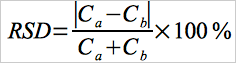 Eq. 5I-1
where, Ca and Cb are concentration values determined from trains A and B respectively. For RSD calculation, the concentration units are unimportant so long as they are consistent.
b. A minimum precision criteria for Reference Method PM data is that RSD for any data pair must be less than 10% as long as the mean PM concentration is greater than 10 mg/unit volume. If the mean PM concentration is less than 10 mg/unit volume higher RSD values are acceptable. At mean PM concentration of 1 mg/unit volume acceptable RSD for paired trains is 25%. Between 1 and 10 mg/unit volume acceptable RSD criteria should be linearly scaled from 25% to 10%. Pairs of manual method data exceeding these RSD criteria should be eliminated from the data set used to develop a PM CEMS correlation or to assess RCA.
13. Method Performance. [Reserved]
14. Pollution Prevention. [Reserved]
15. Waste Management. [Reserved]
16. Alternative Procedures.
Same as Method 5.
17. Bibliography.
Same as Method 5.
18. Tables, Diagrams, flowcharts and Validation Data.
Figure 5I - 1 is a schematic of the sample train.
- Analytical
- Ion Chromatography
- Gas Chromatography
- Gravimetrics
- Ash Resistivity
- Inks/Coatings
- Scrubber Stoichiometry
- Titrations
- Mercury Sorbent Trap
- Engineering
- Express Products
- Rental Instruments
- MET80 Mercury Monitor
- Continuous Emission Monitors
- Gas Sampling Equipment
- Mobile Power Supply
Our Resources
- Technical Resources