- Home
- Careers
- Contact
- About
-
Who we are and what we do. -
Press releases, announcements, and notable corporate information. -
We are looking for a few A people. -
We have over 40 years of innovation to create value for our customers. -
We aim to be the highest value provider of every product and service we offer. -
An easy guide to Probe fundamentals.
-
- Services
-
In additional to the analytical results we normally include an expert analysts summary.
We use our decades of experience to help you better understand your data. -
CleanAir can insures that the project goals and testing are objectives are met.
-
We can ship what you need today. It will work. You get a company of experts when you rent from CleanAir. - Thermal Performance
-
- Rental
-
Our factory reconditioning experts work to make old as good as new. -
CleanAir can provide the services required to care of your emissions measurement or power measurement instruments, no matter the age, model or manufacturer.
-
We deliver rental, emergency, or supplemental instruments and onsite services quickly, with minimal operational interruptions .
-
- Products
Featured Product

UL Listed Mobile Temporary Power
Look professional. Don't risk a OSHA fine, or worse causing your customer to get an OSHA or MSHA fine by using an unsafe mobile power distribution system. The CleanAir Temporary Power cart is UL listed! Read more... -
Reference
-
Overviews of products and services -
Learn about our companies and business -
Detailed technical information about the functioning of our products -
Guides and instructions on proper installation and service -
Guides and instructions on proper installation and service -
Drawings, configuration, materials, and limits useful for the planning and layout.
-
CleanAir's reference of video content -
Publications addressing an issue or topic
-
- Site Map
 Express
 FTIR
FTIR Mercury
 Emission Sampling Equipment
 Instrument Rental
EPA Methods List with Links
US EPA Method 5D - Determination Of Particulate Matter Emissions From Positive Pressure Fabric Filters
NOTE: This method does not include all of the specifications (e.g., equipment and supplies) and procedures (e.g., sampling and analytical) essential to its performance. Some material is incorporated by reference from other methods in this part. Therefore, to obtain reliable results, persons using this method should have a thorough knowledge of at least the following additional test methods: Method 1, Method 2, Method 3, Method 5, Method 17.
Content [ show/hide ].1.0 Scope and Application.
1.1 Analyte.
Particulate matter (PM). No CAS number assigned.
1.2 Applicability.
1.2.1 This method is applicable for the determination of PM emissions from positive pressure fabric filters. Emissions are determined in terms of concentration (mg/m3 or gr/ft3) and emission rate (kg/hr or lb/hr).
1.2.2 The General Provisions of 40 CFR part 60, 60.8(e), require that the owner or operator of an affected facility shall provide performance testing facilities. Such performance testing facilities include sampling ports, safe sampling platforms, safe access to sampling sites, and utilities for testing. It is intended that affected facilities also provide sampling locations that meet the specification for adequate stack length and minimal flow disturbances as described in Method 1. Provisions for testing are often overlooked factors in designing fabric filters or are extremely costly. The purpose of this procedure is to identify appropriate alternative locations and procedures for sampling the emissions from positive pressure fabric filters. The requirements that the affected facility owner or operator provide adequate access to performance testing facilities remain in effect.
1.3 Data Quality Objectives.
Adherence to the requirements of this method will enhance the quality of the data obtained from air pollutant sampling methods.
2.0 Summary of Method.
2.1 Particulate matter is withdrawn isokinetically from the source and collected on a glass fiber filter maintained at a temperature at or above the exhaust gas temperature up to a nominal 120 C (248 ± 25 F). The particulate mass, which includes any material that condenses at or above the filtration temperature, is determined gravimetrically after the removal of uncombined water.
3.0 Definitions. [Reserved]
4.0 Interferences. [Reserved]
5.0 Safety.
5.1 Disclaimer.
This method may involve hazardous materials, operations, and equipment. This test method may not address all of the safety problems associated with its use. It is the responsibility of the user to establish appropriate safety and health practices and to determine the applicability of regulatory limitations prior to performing this test method.
6.0 Equipment and Supplies.
Same as Section 6.0 of either Method 5 or Method 17.
7.0 Reagents and Standards.
Same as Section 7.0 of either Method 5 or Method 17.
8.0 Sample Collection, Preservation, Storage, and Transport.
Same Section 8.0 of either Method 5 or Method 17, except replace Section 8.2.1 of Method 5 with the following:
8.1 Determination of Measurement Site.
The configuration of positive pressure fabric filter structures frequently are not amenable to emission testing according to the requirements of Method 1. Following are several alternatives for determining measurement sites for positive pressure fabric filters.
8.1.1 Stacks Meeting Method 1 Criteria.
Use a measurement site as specified in Method 1, Section 11.1.
8.1.2 Short Stacks Not Meeting Method 1 Criteria.
Use stack extensions and the procedures in Method 1. Alternatively, use flow straightening vanes of the "eggcrate" type (see Figure 5D-1). Locate the measurement site downstream of the straightening vanes at a distance equal to or greater than two times the average equivalent diameter of the vane openings and at least one-half of the overall stack diameter upstream of the stack outlet.
8.1.3 Roof Monitor or Monovent.
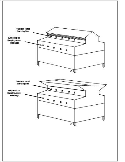
(See Figure 5D-2). For a positive pressure fabric filter equipped with a peaked roof monitor, ridge vent, or other type of monovent, use a measurement site at the base of the monovent. Examples of such locations are shown in Figure 5D-2. The measurement site must be upstream of any exhaust point (e.g., louvered vent).
8.1.4 Compartment Housing.
Sample immediately downstream of the filter bags directly above the tops of the bags as shown in the examples in Figure 5D-2. Depending on the housing design, use sampling ports in the housing walls or locate the sampling equipment within the compartment housing.
8.2 Determination of Number and Location of Traverse Points.
Locate the traverse points according to Method 1, Section 11.3. Because a performance test consists of at least three test runs and because of the varied configurations of positive pressure fabric filters, there are several schemes by which the number of traverse points can be determined and the three test runs can be conducted.
8.2.1 Single Stacks Meeting Method 1 Criteria.
Select the number of traverse points according to Method 1. Sample all traverse points for each test run.
8.2.2 Other Single Measurement Sites.
For a roof monitor or monovent, single compartment housing, or other stack not meeting Method 1 criteria, use at least 24 traverse points. For example, for a rectangular measurement site, such as a monovent, use a balanced 5 x 5 traverse point matrix. Sample all traverse points for each test run.
8.2.3 Multiple Measurement Sites.
Sampling from two or more stacks or measurement sites may be combined for a test run, provided the following guidelines are met:
8.2.3.1 All measurement sites up to 12 must be sampled. For more than 12 measurement sites, conduct sampling on at least 12 sites or 50 percent of the sites, whichever is greater. The measurement sites sampled should be evenly, or nearly evenly, distributed among the available sites; if not, all sites are to be sampled.
8.2.3.2 The same number of measurement sites must be sampled for each test run.
8.2.3.3 The minimum number of traverse points per test run is 24. An exception to the 24-point minimum would be a test combining the sampling from two stacks meeting Method 1 criteria for acceptable stack length, and Method 1 specifies fewer than 12 points per site.
8.2.3.4 As long as the 24 traverse points per test run criterion is met, the number of traverse points per measurement site may be reduced to eight.
8.2.3.5 Alternatively, conduct a test run for each measurement site individually using the criteria in Section 8.2.1 or 8.2.2 to determine the number of traverse points. Each test run shall count toward the total of three required for a performance test. If more than three measurement sites are sampled, the number of traverse points per measurement site may be reduced to eight as long as at least 72 traverse points are sampled for all the tests.
8.2.3.6 The following examples demonstrate the procedures for sampling multiple measurement sites.
8.2.3.6.1 Example 1: A source with nine circular measurement sites of equal areas may be tested as follows: For each test run, traverse three measurement sites using four points per diameter (eight points per measurement site). In this manner, test run number 1 will include sampling from sites 1,2, and 3; run 2 will include samples from sites 4, 5, and 6; and run 3 will include sites 7, 8, and 9. Each test area may consist of a separate test of each measurement site using eight points. Use the results from all nine tests in determining the emission average.
8.2.3.6.2 Example 2: A source with 30 rectangular measurement sites of equal areas may be tested as follows: For each of the three test runs, traverse five measurement sites using a 3 x 3 matrix of traverse points for each site. In order to distribute the sampling evenly over all the available measurement sites while sampling only 50 percent of the sites, number the sites consecutively from 1 to 30 and sample all the even numbered (or odd numbered) sites. Alternatively, conduct a separate test of each of 15 measurement sites using Section 8.2.1 or 8.2.2 to determine the number and location of traverse points, as appropriate.
8.2.3.6.3 Example 3: A source with two measurement sites of equal areas may be tested as follows: For each test of three test runs, traverse both measurement sites, using Section 8.2.3 in determining the number of traverse points. Alternatively, conduct two full emission test runs for each measurement site using the criteria in Section 8.2.1 or 8.2.2 to determine the number of traverse points.
8.2.3.7 Other test schemes, such as random determination of traverse points for a large number of measurement sites, may be used with prior approval from the Administrator.
8.3 Velocity Determination.
8.3.1 The velocities of exhaust gases from positive pressure baghouses are often too low to measure accurately with the Type S pitot tube specified in Method 2 [i.e., velocity head <1.3 mm H2O (0.05 in. H2O)]. For these conditions, measure the gas flow rate at the fabric filter inlet following the procedures outlined in Method 2. Calculate the average gas velocity at the measurement site as shown in Section 12.2 and use this average velocity in determining and maintaining isokinetic sampling rates.
8.3.2 Velocity determinations to determine and maintain isokinetic rates at measurement sites with gas velocities within the range measurable with the Type S pitot tube [i.e., velocity head greater than 1.3 mm H2O (0.05 in. H2O)] shall be conducted according to the procedures outlined in Method 2.
8.4 Sampling.
Follow the procedures specified in Sections 8.1 through 8.6 of Method 5 or Sections 8.1 through 8.25 in Method 17 with the exceptions as noted above.
8.5 sample recovery.
Follow the procedures specified in Section 8.7 of Method 5 or Section 8.2 of Method 17.
9.0 Quality Control.
9.1 Miscellaneous Quality Control Measures.
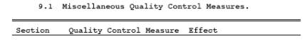
9.2 Volume metering System Checks.
Same as Method 5, Section 9.2.
10.0 Calibration and Standardization.
Same as Section 10.0 of either Method 5 or Method 17.
11.0 Analytical Procedure.
Same as Section 11.0 of either Method 5 or Method 17.
12.0 Data Analysis and Calculations.
Same as Section 12.0 of either Method 5 or Method 17 with the following exceptions:
12.1 Nomenclature.
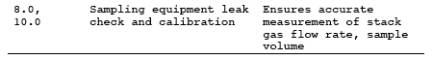
| Ao | = | Measurement site(s) total cross-sectional area, m2 (ft2). |
| Cavg | = | Average concentration of PM for all n runs, mg/scm (gr/scf). |
| Qi | = | Inlet gas volume flow rate, m3/sec (ft3/sec). |
| mi | = | Mass collected for run i of n, mg (gr). |
| To | = | Average temperature of gas at measurement site, K (R). |
| Ti | = | Average temperature of gas at inlet, K (R). |
| Voli | = | Sample volume collected for run i of n, |
| vavg | = | Average gas velocity at the measurement site(s), m/s (ft/s) |
| Qo | = | Total baghouse exhaust volumetric flow rate, m3/sec (ft3/sec). |
| Qd | = | Dilution air flow rate, m3/sec (ft3/sec). |
| Tamb | = | Ambient temperature, (K). |
12.2 Average Gas Velocity.
When following Section 8.3.1, calculate the average gas velocity at the measurement site as follows:
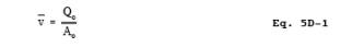
12.3 Volumetric flow Rate.
Total volumetric flow rate may be determined as follows:
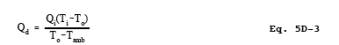
12.4 Dilution Air flow Rate.
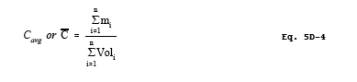
12.5 Average PM Concentration.
For multiple measurement sites, calculate the average PM concentration as follows:
13.0 Method Performance. [Reserved]
14.0 Pollution Prevention. [Reserved]
15.0 Waste Management. [Reserved]
16.0 References.
Same as Method 5, Section 17.0.
17.0 Tables, Diagrams, flowcharts, and Validation Data.
Figure 5D-1. Example of flow Straightening Vanes.
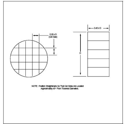
Figure 5D-2. Acceptable Sampling Site Locations for: (a) Peaked Roof; and (b) Ridge Vent Type Fabric filters
- Analytical
- Ion Chromatography
- Gas Chromatography
- Gravimetrics
- Ash Resistivity
- Inks/Coatings
- Scrubber Stoichiometry
- Titrations
- Mercury Sorbent Trap
- Engineering
- Express Products
- Rental Instruments
- MET80 Mercury Monitor
- Continuous Emission Monitors
- Gas Sampling Equipment
- Mobile Power Supply
Our Resources
- Technical Resources