- Home
- Careers
- Contact
- About
-
Who we are and what we do. -
Press releases, announcements, and notable corporate information. -
We are looking for a few A people. -
We have over 40 years of innovation to create value for our customers. -
We aim to be the highest value provider of every product and service we offer. -
An easy guide to Probe fundamentals.
-
- Services
-
In additional to the analytical results we normally include an expert analysts summary.
We use our decades of experience to help you better understand your data. -
CleanAir can insures that the project goals and testing are objectives are met.
-
We can ship what you need today. It will work. You get a company of experts when you rent from CleanAir. - Thermal Performance
-
- Rental
-
Our factory reconditioning experts work to make old as good as new. -
CleanAir can provide the services required to care of your emissions measurement or power measurement instruments, no matter the age, model or manufacturer.
-
We deliver rental, emergency, or supplemental instruments and onsite services quickly, with minimal operational interruptions .
-
- Products
Featured Product

UL Listed Mobile Temporary Power
Look professional. Don't risk a OSHA fine, or worse causing your customer to get an OSHA or MSHA fine by using an unsafe mobile power distribution system. The CleanAir Temporary Power cart is UL listed! Read more... -
Reference
-
Overviews of products and services -
Learn about our companies and business -
Detailed technical information about the functioning of our products -
Guides and instructions on proper installation and service -
Guides and instructions on proper installation and service -
Drawings, configuration, materials, and limits useful for the planning and layout.
-
CleanAir's reference of video content -
Publications addressing an issue or topic
-
- Site Map
 Express
 FTIR
FTIR Mercury
 Emission Sampling Equipment
 Instrument Rental
EPA Methods List with Links
US EPA Method 28 - Certification And Auditing Of Wood Heaters
NOTE: This method does not include all of the specifications (e.g., equipment and supplies) and procedures (e.g., sampling and analytical) essential to its performance. Some material is incorporated by reference from other methods in this part. Therefore, to obtain reliable results, persons using this method should have a thorough knowledge of at least the following additional test methods: Method 1, Method 2, Method 3, Method 4, Method 5, Method 5G, Method 5H, Method 6, Method 6C, and Method 16A.
1.0 Scope and Application.
1.1 Analyte.
Particulate matter (PM). No CAS number assigned.
1.2 Applicability.
This method is applicable for the certification and auditing of wood heaters, including pellet burning wood heaters.
1.3 Data Quality Objectives.
Adherence to the requirements of this method will enhance the quality of the data obtained from air pollutant sampling methods.
2.0 Summary of Method.
2.1 Particulate matter emissions are measured from a wood heater burning a prepared test fuel crib in a test facility maintained at a set of prescribed conditions. Procedures for determining burn rates and particulate emission rates and for reducing data are provided.
3.0 Definitions.
3.1 2 4 or 4 4 means two inches by four inches or four inches by four inches (50 mm by 100 mm or 100 mm by 100 mm), as nominal dimensions for lumber.
3.2 Burn rate means the rate at which test fuel is consumed in a wood heater. Measured in kilograms or lbs of wood (dry basis) per hour (kg/hr or lb/hr).
3.3 Certification or audit test means a series of at least four test runs conducted for certification or audit purposes that meets the burn rate specifications in Section 8.4.
3.4 Firebox means the chamber in the wood heater in which the test fuel charge is placed and combusted.
3.5 Height means the vertical distance extending above the loading door, if fuel could reasonably occupy that space, but not more than 2 inches above the top (peak height) of the loading door, to the floor of the firebox (i.e., below a permanent grate) if the grate allows a 1-inch diameter piece of wood to pass through the grate, or, if not, to the top of the grate. Firebox height is not necessarily uniform but must account for variations caused by internal baffles, air channels, or other permanent obstructions.
3.6 Length means the longest horizontal fire chamber dimension that is parallel to a wall of the chamber.
3.7 Pellet burning wood heater means a wood heater which meets the following criteria: (1) The manufacturer makes no reference to burning cord wood in advertising or other literature, (2) the unit is safety listed for pellet fuel only, (3) the unit operating and instruction manual must state that the use of cordwood is prohibited by law, and (4) the unit must be manufactured and sold including the hopper and auger combination as integral parts.
3.8 Secondary air supply means an air supply that introduces air to the wood heater such that the burn rate is not altered by more than 25 percent when the secondary air supply is adjusted during the test run. The wood heater manufacturer can document this through design drawings that show the secondary air is introduced only into a mixing chamber or secondary chamber outside the firebox.
3.9 Test facility means the area in which the wood heater is installed, operated, and sampled for emissions.
3.10 Test fuel charge means the collection of test fuel pieces placed in the wood heater at the start of the emission test run.
3.11 Test fuel crib means the arrangement of the test fuel charge with the proper spacing requirements between adjacent fuel pieces.
3.12 Test fuel loading density means the weight of the as-fired test fuel charge per unit volume of usable firebox.
3.13 Test fuel piece means the 2 4 or 4 4 wood piece cut to the length required for the test fuel charge and used to construct the test fuel crib.
3.14 Test run means an individual emission test which encompasses the time required to consume the mass of the test fuel charge.
3.15 Usable firebox volume means the volume of the firebox determined using its height, length, and width as defined in this section.
3.16 Width means the shortest horizontal fire chamber dimension that is parallel to a wall of the chamber.
3.17 Wood heater means an enclosed, woodburning appliance capable of and intended for space heating or domestic water heating, as defined in the applicable regulation.
4.0 Interferences. [Reserved]
5.0 Safety.
5.1 Disclaimer. This method may involve hazardous materials, operations, and equipment. This test method may not address all of the safety problems associated with its use. It is the responsibility of the user of this test method to establish appropriate safety and health practices and to determine the applicability of regulatory limitations prior to performing this test method.
6.0 Equipment and Supplies.
Same as Section 6.0 of either Method 5G or Method 5H, with the addition of the following:
6.1 Insulated Solid Pack Chimney. For installation of wood heaters. Solid pack insulated chimneys shall have a minimum of 2.5 cm (1 in.) solid pack insulating material surrounding the entire flue and possess a label demonstrating conformance to U.L. 103 (incorporated by reference - see 60.17).
6.2 Platform Scale and Monitor. For monitoring of fuel load weight change. The scale shall be capable of measuring weight to within 0.05 kg (0.1 lb) or 1 percent of the initial test fuel charge weight, whichever is greater.
6.3 Wood Heater temperature Monitors. Seven, each capable of measuring temperature to within 1.5 percent of expected absolute temperatures.
6.4 Test Facility temperature Monitor. A thermocouple located centrally in a vertically oriented 150 mm (6 in.) long, 50 mm (2 in.) diameter pipe shield that is open at both ends, capable of measuring temperature to within 1.5 percent of expected temperatures.
6.5 Balance (optional). Balance capable of weighing the test fuel charge to within 0.05 kg (0.1 lb).
6.6 Moisture meter. Calibrated electrical resistance meter for measuring test fuel moisture to within 1 percent moisture content.
6.7 Anemometer. Device capable of detecting air velocities less than 0.10 m/sec (20 ft/min), for measuring air velocities near the test appliance.
6.8 barometer. Mercury, aneroid or other barometer capable of measuring atmospheric pressure to within 2.5 mm Hg (0.1 in. Hg).
6.9 Draft Gauge. Electromanometer or other device for the determination of flue draft or static pressure readable to within 0.50 Pa (0.002 in. H2O).
6.10 Humidity Gauge. Psychrometer or hygrometer for measuring room humidity.
6.11 Wood Heater flue.
6.11.1 Steel flue pipe extending to 2.6 ± 0.15 m (8.5 ± 0.5 ft) above the top of the platform scale, and above this level, insulated solid pack type chimney extending to 4.6 ± 0.3 m (15 ± 1 ft) above the platform scale, and of the size specified by the wood heater manufacturer. This applies to both freestanding and insert type wood heaters.
6.11.2 Other chimney types (e.g., solid pack insulated pipe) may be used in place of the steel flue pipe if the wood heater manufacturer's written appliance specifications require such chimney for home installation (e.g., zero clearance wood heater inserts). Such alternative chimney or flue pipe must remain and be sealed with the wood heater following the certification test.
6.12 Test Facility. The test facility shall meet the following requirements during testing:
6.12.1 The test facility temperature shall be maintained between 18 and 32 EC (65 and 90 EF) during each test run.
6.12.2 Air velocities within 0.6 m (2 ft) of the test appliance and exhaust system shall be less than 0.25 m/sec (50 ft/min) without fire in the unit.
6.12.3 The flue shall discharge into the same space or into a space freely communicating with the test facility. Any hood or similar device used to vent combustion products shall not induce a draft greater than 1.25 Pa (0.005 in. H2O) on the wood heater measured when the wood heater is not operating.
6.12.4 For test facilities with artificially induced
barometric pressures (e.g., pressurized chambers), the barometric pressure in the test facility shall not exceed 775 mm Hg (30.5 in. Hg) during any test run.
7.0 Reagents and Standards.
Same as Section 6.0 of either Method 5G or Method 5H, with the addition of the following:
7.1 Test Fuel.
The test fuel shall conform to the following requirements:
7.1.1 Fuel Species. Untreated, air-dried, Douglas fir lumber. Kiln-dried lumber is not permitted. The lumber shall be certified C grade (standard) or better Douglas fir by a lumber grader at the mill of origin as specified in the West Coast Lumber Inspection Bureau Standard No. 16 (incorporated by reference - see 60.17).
7.1.2 Fuel Moisture. The test fuel shall have a moisture content range between 16 to 20 percent on a wet basis (19 to 25 percent dry basis). Addition of moisture to previously dried wood is not allowed. It is recommended that the test fuel be stored in a temperature and humidity-controlled room.
7.1.3 Fuel temperature. The test fuel shall be at the test facility temperature of 18 to 32 EC (65 to 90 EF).
7.1.4 Fuel Dimensions. The dimensions of each test fuel piece shall conform to the nominal measurements of 2 4 and 4 4 lumber. Each piece of test fuel (not including spacers) shall be of equal length, except as necessary to meet requirements in Section 8.8, and shall closely approximate 5/6 the dimensions of the length of the usable firebox. The fuel piece dimensions shall be determined in relation to the appliance's firebox volume according to guidelines listed below:
7.1.4.1 If the usable firebox volume is less than or equal to 0.043 m3 (1.5 ft3), use 2 4 lumber.
7.1.4.2 If the usable firebox volume is greater than 0.043 m3 (1.5 ft3) and less than or equal to 0.085 m3 (3.0 ft3), use 2 4 and 4 4 lumber. About half the weight of the test fuel charge shall be 2 4 lumber, and the remainder shall be 4 4 lumber.
7.1.4.3 If the usable firebox volume is greater than 0.085 m3 (3.0 ft3), use 4 4 lumber.
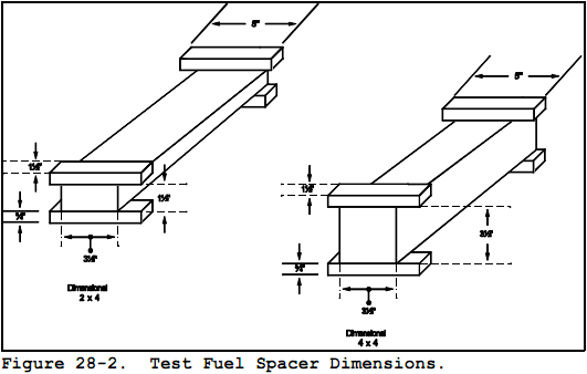
7.2 Test Fuel Spacers.
Air-dried, Douglas fir lumber meeting the requirements outlined in Sections 7.1.1 through 7.1.3. The spacers shall be 130 40 20 mm (5 1.5 0.75 in.).
8.0 Sample Collection, Preservation, Storage, and Transport.
8.1 Test Run Requirements.
8.1.1 Burn Rate Categories. One emission test run is required in each of the following burn rate categories:
BURN RATE CATEGORIES
[Average kg/hr (lb/hr), dry basis)
| Category 1 | Category 2 | Category 3 | Category 4 |
|---|---|---|---|
| < 0.80 (< 1.76) | 0.80 to 1.25 (1.76 to 2.76) | 1.25 to 1.90 (2.76 to 4.19)a | Maximum burn rate |
8.1.1.1 Maximum Burn Rate. For Category 4, the wood heater shall be operated with the primary air supply inlet controls fully open (or, if thermostatically controlled, the thermostat shall be set at maximum heat output) during the entire test run, or the maximum burn rate setting specified by the manufacturer's written instructions.
8.1.1.2 Other Burn Rate Categories. For burn rates in Categories 1 through 3, the wood heater shall be operated with the primary air supply inlet control, or other mechanical control device, set at a predetermined position necessary to obtain the average burn rate required for the category.
8.1.1.3 Alternative Burn Rates for Burn Rate Categories 1 and 2.
8.1.1.3.1 If a wood heater cannot be operated at a burn rate below 0.80 kg/hr (1.76 lb/hr), two test runs shall be conducted with burn rates within Category 2. If a wood
1411 heater cannot be operated at a burn rate below 1.25 kg/hr (2.76 lb/hr), the flue shall be dampered or the air supply otherwise controlled in order to achieve two test runs within Category 2.
8.1.1.3.2 Evidence that a wood heater cannot be operated at a burn rate less than 0.80 kg/hr shall include documentation of two or more attempts to operate the wood heater in burn rate Category 1 and fuel combustion has stopped, or results of two or more test runs demonstrating that the burn rates were greater than 0.80 kg/hr when the air supply controls were adjusted to the lowest possible position or settings. Stopped fuel combustion is evidenced when an elapsed time of 30 minutes or more has occurred without a measurable (< 0.05 kg (0.1 lb) or 1.0 percent, whichever is greater) weight change in the test fuel charge. See also Section 8.8.3. Report the evidence and the reasoning used to determine that a test in burn rate Category 1 cannot be achieved; for example, two unsuccessful attempts to operate at a burn rate of 0.4 kg/hr are not sufficient evidence that burn rate Category 1 cannot be achieved.
NOTE: After July 1, 1990, if a wood heater cannot be operated at a burn rate less than 0.80 kg/hr, at least one test run with an average burn rate of 1.00 kg/hr or less shall be conducted. Additionally, if flue dampering must be used to achieve burn rates below 1.25 kg/hr (or 1.0 kg/hr), results from a test run conducted at burn rates below 0.90 kg/hr need not be reported or included in the test run average provided that such results are replaced with results from a test run meeting the criteria above.
8.2 Catalytic Combustor and Wood Heater Aging.
The catalyst-equipped wood heater or a wood heater of any type shall be aged before the certification test begins. The aging procedure shall be conducted and documented by a testing laboratory accredited according to procedures in 60.535 of 40 CFR part 60.
8.2.1 Catalyst-equipped Wood Heater. Operate the catalyst-equipped wood heater using fuel meeting the specifications outlined in Sections 7.1.1 through 7.1.3, or cordwood with a moisture content between 15 and 25 percent on a wet basis. Operate the wood heater at a medium burn rate (Category 2 or 3) with a new catalytic combustor in place and in operation for at least 50 hours. Record and report hourly catalyst exit temperature data (Section 8.6.2) and the hours of operation.
8.2.2 Non-Catalyst Wood Heater. Operate the wood heater using the fuel described in Section 8.4.1 at a medium burn rate for at least 10 hours. Record and report the hours of operation.
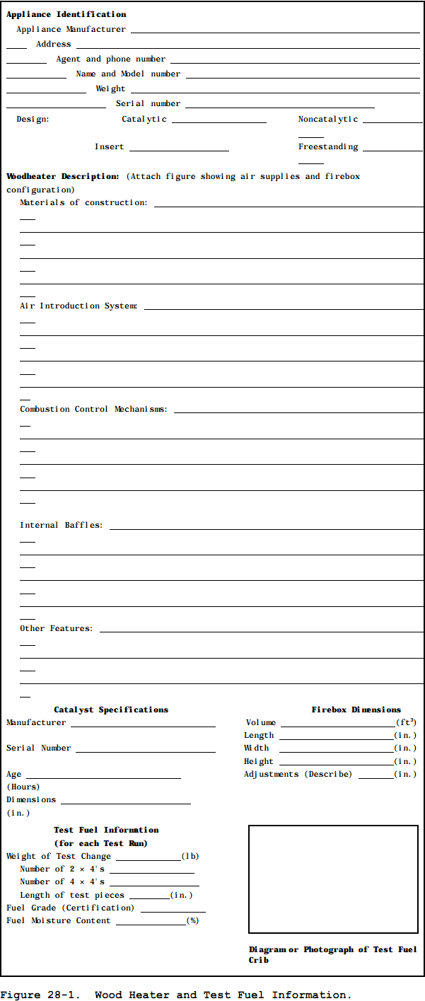
8.3 Pretest Recordkeeping.
Record the test fuel charge dimensions and weights, and wood heater and catalyst descriptions as shown in the example in Figure 28-1.
8.4 Wood Heater Installation.
Assemble the wood heater appliance and parts in conformance with the manufacturer's written installation instructions. Place the wood heater centrally on the platform scale and connect the wood heater to the flue described in Section 6.11. Clean the flue with an appropriately sized, wire chimney brush before each certification test.
8.5 Wood Heater temperature Monitors.
8.5.1 For catalyst-equipped wood heaters, locate a temperature monitor (optional) about 25 mm (1 in.) upstream of the catalyst at the centroid of the catalyst face area, and locate a temperature monitor (mandatory) that will indicate the catalyst exhaust temperature. This temperature monitor is centrally located within 25 mm (1 in.) downstream at the centroid of catalyst face area. Record these locations.
8.5.2 Locate wood heater surface temperature monitors at five locations on the wood heater firebox exterior surface. Position the temperature monitors centrally on the top surface, on two sidewall surfaces, and on the bottom and back surfaces. Position the monitor sensing tip on the firebox exterior surface inside of any heat shield, air circulation walls, or other wall or shield separated from the firebox exterior surface. Surface temperature locations for unusual design shapes (e.g., spherical, etc.) shall be positioned so that there are four surface temperature monitors in both the vertical and horizontal planes passing at right angles through the centroid of the firebox, not including the fuel loading door (total of five temperature monitors).
8.6 Test Facility Conditions.
8.6.1 Locate the test facility temperature monitor on the horizontal plane that includes the primary air intake opening for the wood heater. Locate the temperature monitor 1 to 2 m (3 to 6 ft) from the front of the wood heater in the 90E sector in front of the wood heater.
8.6.2 Use an anemometer to measure the air velocity. Measure and record the room air velocity before the pretest ignition period (Section 8.7) and once immediately following the test run completion.
8.6.3 Measure and record the test facility's ambient relative humidity, barometric pressure, and temperature before and after each test run.
8.6.4 Measure and record the flue draft or static pressure in the flue at a location no greater than 0.3 m (1 ft) above the flue connector at the wood heater exhaust during the test run at the recording intervals (Section 8.8.2).
8.7 Wood Heater Firebox Volume.
8.7.1 Determine the firebox volume using the definitions for height, width, and length in Section 3. Volume adjustments due to presence of firebrick and other permanent fixtures may be necessary. Adjust width and length dimensions to extend to the metal wall of the wood heater above the firebrick or permanent obstruction if the firebrick or obstruction extending the length of the side(s) or back wall extends less than one-third of the usable firebox height. Use the width or length dimensions inside the firebrick if the firebrick extends more than one-third of the usable firebox height. If a log retainer or grate is a permanent fixture and the manufacturer recommends that no fuel be placed outside the retainer, the area outside of the retainer is excluded from the firebox volume calculations.
8.7.2 In general, exclude the area above the ash lip if that area is less than 10 percent of the usable firebox volume. Otherwise, take into account consumer loading practices. For instance, if fuel is to be loaded front-to-back, an ash lip may be considered usable firebox volume.
8.7.3 Include areas adjacent to and above a baffle (up to two inches above the fuel loading opening) if four inches or more horizontal space exist between the edge of the baffle and a vertical obstruction (e.g., sidewalls or air channels).
8.8 Test Fuel Charge.
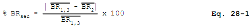
8.8.1 Prepare the test fuel pieces in accordance with the specifications outlined in Sections 7.1 and 7.2. Determine the test fuel moisture content with a calibrated electrical resistance meter or other equivalent performance meter. If necessary, convert fuel moisture content values from dry basis (%Md) to wet basis (%Mw) in Section 12.2 using Equation 28-1. Determine fuel moisture for each fuel piece (not including spacers) by averaging at least three moisture meter readings, one from each of three sides, measured parallel to the wood grain. Average all the readings for all the fuel pieces in the test fuel charge. If an electrical resistance type meter is used, penetration of insulated electrodes shall be one-fourth the thickness of the test fuel piece or 19 mm (0.75 in.), whichever is greater. Measure the moisture content within a 4-hour period prior to the test run. Determine the fuel temperature by measuring the temperature of the room where the wood has been stored for at least 24 hours prior to the moisture determination.
8.8.2 Attach the spacers to the test fuel pieces with uncoated, ungalvanized nails or staples as illustrated in Figure 28-2. Attachment of spacers to the top of the test fuel piece(s) on top of the test fuel charge is optional.
8.8.3 To avoid stacking difficulties, or when a whole number of test fuel pieces does not result, all piece lengths shall be adjusted uniformly to remain within the specified loading density. The shape of the test fuel crib shall be geometrically similar to the shape of the firebox volume without resorting to special angular or round cuts on the individual fuel pieces.
8.8.4 The test fuel loading density shall be 112 ± 11.2 kg/m3 (7 ± 0.7 lb/ft3) of usable firebox volume on a wet basis.
8.9 Sampling equipment.
Prepare the sampling equipment as defined by the selected method (i.e., either Method 5G or Method 5H). Collect one particulate emission sample for each test run.
8.10 Secondary Air Adjustment Validation.
8.10.1 If design drawings do not show the introduction of secondary air into a chamber outside the firebox (see "secondary air supply" under Section 3.0, Definitions), conduct a separate test of the wood heater's secondary air supply. Operate the wood heater at a burn rate in Category 1 (Section 8.1.1) with the secondary air supply operated following the manufacturer's written instructions. Start the secondary air validation test run as described in Section 8.8.1, except no emission sampling is necessary and burn rate data shall be recorded at 5-minute intervals.
8.10.2 After the start of the test run, operate the wood heater with the secondary air supply set as per the manufacturer's instructions, but with no adjustments to this setting. After 25 percent of the test fuel has been consumed, adjust the secondary air supply controls to another setting, as per the manufacturer's instructions. Record the burn rate data (5-minute intervals) for 20 minutes following the air supply adjustment.
8.10.3 Adjust the air supply control(s) to the original position(s), operate at this condition for at least 20 minutes, and repeat the air supply adjustment procedure above. Repeat the procedure three times at equal intervals over the entire burn period as defined in Section 8.8. If the secondary air adjustment results in a burn rate change of more than an average of 25 percent between the 20-minute periods before and after the secondary adjustments, the secondary air supply shall be considered a primary air supply, and no adjustment to this air supply is allowed during the test run.
8.10.4 The example sequence below describes a typical secondary air adjustment validation check. The first cycle begins after at least 25 percent of the test fuel charge has been consumed.
| Cycle 1 | Part 1, sec air adjusted to final position - 20 min Part 2, sec air adjusted to initial position - 20 min Part 3, sec air adjusted to final position - 20 min |
| Cycle 2 | Part 1, sec air adjusted to final position - 20 min Part 2, sec air adjusted to initial position - 20 min Part 3, sec air adjusted to final position - 20 min |
| Cycle 3 | Part 1, sec air adjusted to final position - 20 min Part 2, sec air adjusted to initial position - 20 min Part 3, sec air adjusted to final position - 20 min |
Note that the cycles may overlap; that is, Part 3 of Cycle 1 may coincide in part or in total with Part 1 of Cycle 2.
The calculation of the secondary air percent effect for this example is as follows:
8.11 Pretest Ignition.
Build a fire in the wood heater in accordance with the manufacturer's written instructions.
8.11.1 Pretest Fuel Charge. Crumpled newspaper loaded with kindling may be used to help ignite the pretest fuel. The pretest fuel, used to sustain the fire, shall meet the same fuel requirements prescribed in Section 7.1. The pretest fuel charge shall consist of whole 2 4's that are no less than 1/3 the length of the test fuel pieces. Pieces of 4 4 lumber in approximately the same weight ratio as for the test fuel charge may be added to the pretest fuel charge.
8.11.2 Wood Heater Operation and Adjustments. Set the air inlet supply controls at any position that will maintain combustion of the pretest fuel load. At least one hour before the start of the test run, set the air supply controls at the approximate positions necessary to achieve the burn rate desired for the test run. Adjustment of the air supply controls, fuel addition or subtractions, and coalbed raking shall be kept to a minimum but are allowed up to 15 minutes prior to the start of the test run. For the purposes of this method, coalbed raking is the use of a metal tool (poker) to stir coals, break burning fuel into smaller pieces, dislodge fuel pieces from positions of poor combustion, and check for the condition of uniform charcoalization. Record all adjustments made to the air supply controls, adjustments to and additions or subtractions of fuel, and any other changes to wood heater operations that occur during pretest ignition period. Record fuel weight data and wood heater temperature measurements at 10-minute intervals during the hour of the pretest ignition period preceding the start of the test run. During the 15-minute period prior to the start of the test run, the wood heater loading door shall not be open more than a total of 1 minute. Coalbed raking is the only adjustment allowed during this period.
NOTE: One purpose of the pretest ignition period is to achieve uniform charcoalization of the test fuel bed prior to loading the test fuel charge. Uniform charcoalization is a general condition of the test fuel bed evidenced by an absence of large pieces of burning wood in the coal bed and the remaining fuel pieces being brittle enough to be broken into smaller charcoal pieces with a metal poker. Manipulations to the fuel bed prior to the start of the test run should be done to achieve uniform charcoalization while maintaining the desired burn rate. In addition, some wood heaters (e.g., high mass units) may require extended pretest burn time and fuel additions to reach an initial average surface temperature sufficient to meet the thermal equilibrium criteria in Section 8.3.
8.11.3 The weight of pretest fuel remaining at the start of the test run is determined as the difference between the weight of the wood heater with the remaining pretest fuel and the tare weight of the cleaned, dry wood heater with or without dry ash or sand added consistent with the manufacturer's instructions and the owner's manual. The tare weight of the wood heater must be determined with the wood heater (and ash, if added) in a dry condition.
8.12 Test Run.
Complete a test run in each burn rate category, as follows:
8.12.1 Test Run Start.
8.12.1.1 When the kindling and pretest fuel have been consumed to leave a fuel weight between 20 and 25 percent of the weight of the test fuel charge, record the weight of the fuel remaining and start the test run. Record and report any other criteria, in addition to those specified in this section, used to determine the moment of the test run start (e.g., firebox or catalyst temperature), whether such criteria are specified by the wood heater manufacturer or the testing laboratory. Record all wood heater individual surface temperatures, catalyst temperatures, any initial sampling method measurement values, and begin the particulate emission sampling. Within 1 minute following the start of the test run, open the wood heater door, load the test fuel charge, and record the test fuel charge weight. Recording of average, rather than individual, surface temperatures is acceptable for tests conducted in accordance with 60.533(o)(3)(i) of 40 CFR part 60.
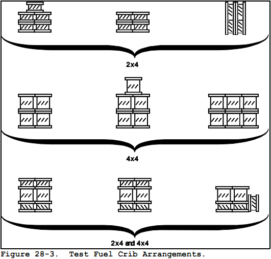
8.12.1.2 Position the fuel charge so that the spacers are parallel to the floor of the firebox, with the spacer edges abutting each other. If loading difficulties result, some fuel pieces may be placed on edge. If the usable firebox volume is between 0.043 and 0.085 m3 (1.5 and 3.0 ft3), alternate the piece sizes in vertical stacking layers to the extent possible. For example, place 2 4's on the bottom layer in direct contact with the coal bed and 4 4's on the next layer, etc. (See Figure 28-3). Position the fuel pieces parallel to each other and parallel to the longest wall of the firebox to the extent possible within the specifications in Section 8.8.
8.12.1.3 Load the test fuel in appliances having unusual or unconventional firebox design maintaining air space intervals between the test fuel pieces and in conformance with the manufacturer's written instructions. For any appliance that will not accommodate the loading arrangement specified in the paragraph above, the test facility personnel shall contact the Administrator for an alternative loading arrangement.
8.12.1.4 The wood heater door may remain open and the air supply controls adjusted up to five minutes after the start of the test run in order to make adjustments to the test fuel charge and to ensure ignition of the test fuel charge has occurred. Within the five minutes after the start of the test run, close the wood heater door and adjust the air supply controls to the position determined to produce the desired burn rate. No other adjustments to the air supply controls or the test fuel charge are allowed (except as specified in Sections 8.12.3 and 8.12.4) after the first five minutes of the test run. Record the length of time the wood heater door remains open, the adjustments to the air supply controls, and any other operational adjustments.
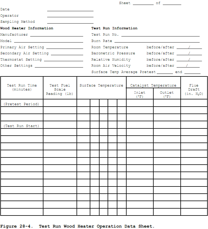
8.12.2 Data Recording.
Record on a data sheet similar to that shown in Figure 28-4, at intervals no greater than 10 minutes, fuel weight data, wood heater individual surface and catalyst temperature measurements, other wood heater operational data (e.g., draft), test facility temperature and sampling method data.
8.12.3 Test Fuel Charge Adjustment.
The test fuel charge may be adjusted (i.e., repositioned) once during a test run if more than 60 percent of the initial test fuel charge weight has been consumed and more than 10 minutes have elapsed without a measurable (< 0.05 kg (0.1 lb) or 1.0 percent, whichever is greater) weight change. The time used to make this adjustment shall be less than 15 seconds.
8.12.4 Air Supply Adjustment.
Secondary air supply controls may be adjusted once during the test run following the manufacturer's written instructions (see Section 8.10).
No other air supply adjustments are run. Recording of wood heater flue run is optional for tests conducted 60.533(o)(3)(i) of 40 CFR part 60.
allowed during the test draft during the test in accordance with
8.12.5 Auxiliary Wood Heater equipment Operation.
Heat exchange blowers sold with the wood heater shall be operated during the test run following the manufacturer's written instructions. If no manufacturer's written instructions are available, operate the heat exchange blower in the "high" position. (Automatically operated blowers shall be operated as designed.) Shaker grates, by-pass controls, or other auxiliary equipment may be adjusted only one time during the test run following the manufacturer's written instructions. Record all adjustments on a wood heater operational written record.
NOTE: If the wood heater is sold with a heat exchange blower as an option, test the wood heater with the heat exchange blower operating as described in Sections 8.1 through 8.12 and report the results. As an alternative to repeating all test runs without the heat exchange blower operating, one additional test run may be without the blower operating as described in Section 8.12.5 at a burn rate in Category 2 (Section 8.1.1). If the emission rate resulting from this test run without the blower operating is equal to or less than the emission rate plus 1.0 g/hr (0.0022 lb/hr) for the test run in burn rate Category 2 with the blower operating, the wood heater may be considered to have the same average emission rate with or without the blower operating. Additional test runs without the blower operating are unnecessary.
8.13 Test Run Completion.
Continue emission sampling and wood heater operation for 2 hours. The test run is completed when the remaining weight of the test fuel charge is 0.00 kg (0.0 lb). End the test run when the scale has indicated a test fuel charge weight of 0.00 kg (0.0 lb) or less for 30 seconds. At the end of the test run, stop the particulate sampling, and record the final fuel weight, the run time, and all final measurement values.
8.14 Wood Heater Thermal Equilibrium.
The average of the wood heater surface temperatures at the end of the test run shall agree with the average surface temperature at the start of the test run to within 70 EC (126 EF).
8.15 Consecutive Test Runs.
Test runs on a wood heater may be conducted consecutively provided that a minimum one-hour interval occurs between test runs.
8.16 Additional Test Runs.
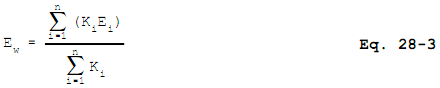
The testing laboratory may conduct more than one test run in each of the burn rate categories specified in Section 8.1.1. If more than one test run is conducted at a specified burn rate, the results from at least two-thirds of the test runs in that burn rate category shall be used in calculating the weighted average emission rate (see Section 12.2). The measurement data and results of all test runs shall be reported regardless of which values are used in calculating the weighted average emission rate (see NOTE in Section 8.1).
9.0 Quality Control.
Same as Section 9.0 of either Method 5G or Method 5H.
10.0 Calibration and Standardizations.
Same as Section 10.0 of either Method 5G or Method 5H, with the addition of the following:
10.1 Platform Scale.
Perform a multi-point calibration (at least five points spanning the operational range) of the platform scale before its initial use. The scale manufacturer's calibration results are sufficient for this purpose. Before each certification test, audit the scale with the wood heater in place by weighing at least one calibration weight (Class F) that corresponds to between 20 percent and 80 percent of the expected test fuel charge weight. If the scale cannot reproduce the value of the calibration weight within 0.05 kg (0.1 lb) or 1 percent of the expected test fuel charge weight, whichever is greater, recalibrate the scale before use with at least five calibration weights spanning the operational range of the scale.
10.2 Balance (optional).
Calibrate as described in Section 10.1.
10.3 temperature Monitor.
Calibrate as in Method 2, Section 4.3, before the first certification test and semiannually thereafter.
10.4 Moisture meter.
Calibrate as per the manufacturer's instructions before each certification test.
10.5 Anemometer.
Calibrate the anemometer as specified by the manufacturer's instructions before the first certification test and semiannually thereafter.
10.6 barometer.
Calibrate against a mercury barometer before the first certification test and semiannually thereafter.
10.7 Draft Gauge.
Calibrate as per the manufacturer's instructions; a liquid manometer does not require calibration.
10.8 Humidity Gauge.
Calibrate as per the manufacturer's instructions before the first certification test and semiannually thereafter.
11.0 Analytical Procedures.
Same as Section 11.0 of either Method 5G or Method 5H.
12.0 Data Analysis and Calculations.
Same as Section 12.0 of either Method 5G or Method 5H, with the addition of the following:
12.1 Nomenclature.
| BR | = | Dry wood burn rate, kg/hr (lb/hr) |
| Ei | = | Emission rate for test run, i, from Method 5G or 5H, g/hr (lb/hr) |
| Ew | = | Weighted average emission rate, g/hr (lb/hr) |
| ki | = | Test run weighting factor = Pi+1 ) Pi-1 |
| %Md | = | Fuel moisture content, dry basis, percent |
| %Mw | = | Average moisture in test fuel charge, wet basis, percent. |
| n | = | Total number of test runs. |
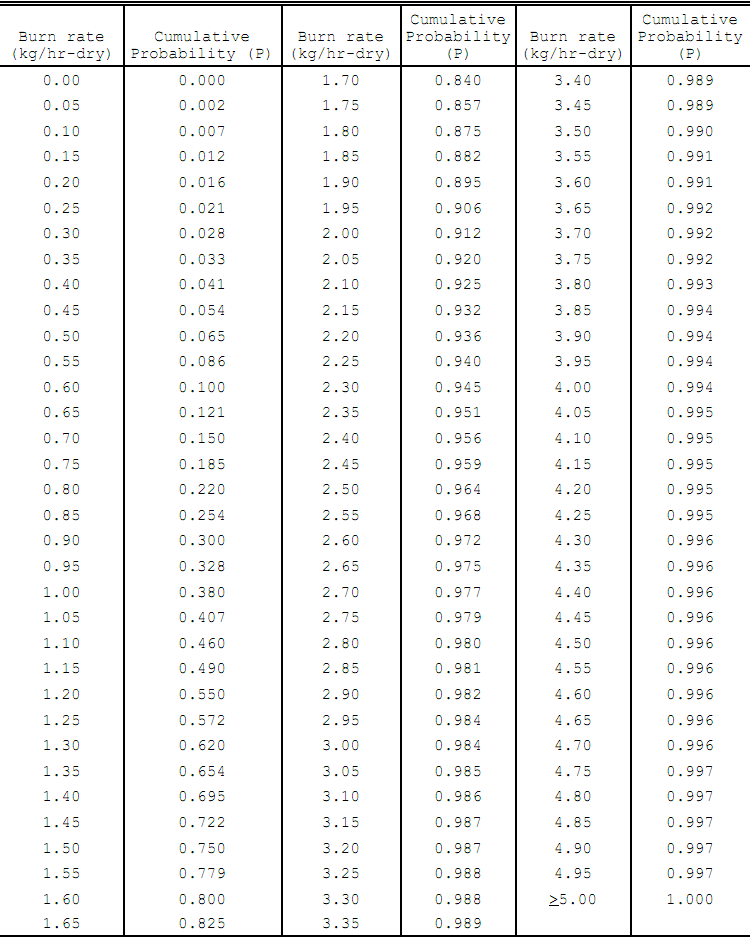
| Pi | = | Probability for burn rate during test run, i, obtained from Table 28-1. Use linear interpolation to determine probability values for burn rates between those listed on the table. |
| Wwd | = | Total mass of wood burned during the test run, kg (lb). |
12.2 Wet Basis Fuel Moisture Content.
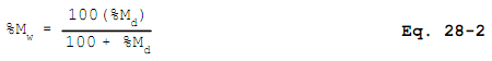
12.3 Weighted Average Emission Rate. Calculate the weighted average emission rate (Ew) using Equation 28-1:
NOTE: Po always equals 0, P(n+1) always equals 1, P1 corresponds to the probability of the lowest recorded burn rate, P2 corresponds to the probability of the next lowest burn rate, etc. An example calculation is in Section 12.3.1.
12.3.1 Example Calculation of Weighted Average Emission Rate.
= 4.69 g/hr
12.4 Average Wood Heater Surface temperatures.
Calculate the average of the wood heater surface temperatures for the start of the test run (Section 8.12.1) and for the test run completion (Section 8.13). If the two average temperatures do not agree within 70 EC (125 EF), report the test run results, but do not include the test run results in the test average. Replace such test run results with results from another test run in the same burn rate category.
12.5 Burn Rate.
Calculate the burn rate (BR) using Equation 28-3:
.png)
12.6 Reporting Criteria. Submit both raw and reduced test data for wood heater tests.
12.6.1 Suggested Test Report Format.
12.6.1.1 Introduction.
12.6.1.1.1 Purpose of test)certification, audit, efficiency, research and development.
12.6.1.1.2 Wood heater identification)manufacturer, model number, catalytic/noncatalytic, options.
12.6.1.1.3 Laboratory)name, location (altitude), participants.
12.6.1.1.4 Test information)date wood heater received, date of tests, sampling methods used, number of test runs.
12.6.1.2 Summary and Discussion of Results
12.6.1.2.1 Table of results (in order of increasing burn rate))test run number, burn rate, particulate emission rate, efficiency (if determined), averages (indicate which test runs are used).
12.6.1.2.2 Summary of other data)test facility conditions, surface temperature averages, catalyst temperature averages, pretest fuel weights, test fuel charge weights, run times.
12.6.1.2.3 Discussion)Burn rate categories achieved, test run result selection, specific test run problems and solutions.
12.6.1.3 Process Description.
12.6.1.3.1 Wood heater dimensions)volume, height, width, lengths (or other linear dimensions), weight, volume adjustments.
12.6.1.3.2 Firebox configuration)air supply locations and operation, air supply introduction location, refractory location and dimensions, catalyst location, baffle and by-pass location and operation (include line drawings or photographs).
12.6.1.3.3 Process operation during test)air supply settings and adjustments, fuel bed adjustments, draft.
12.6.1.3.4 Test fuel)test fuel properties (moisture and temperature), test fuel crib description (include line drawing or photograph), test fuel loading density.
12.6.1.4 Sampling Locations
12.6.1.4.1 Describe sampling location relative to wood heater. Include drawing or photograph.
12.6.1.5 Sampling and Analytical Procedures
12.6.1.5.1 Sampling methods)brief reference to operational and sampling procedures and optional and alternative procedures used.
12.6.1.5.2 Analytical methods)brief description of sample recovery and analysis procedures.
12.6.1.6 Quality Control and Assurance Procedures and Results
12.6.1.6.1 calibration procedures and results)certification procedures, sampling and analysis procedures.
12.6.1.6.2 Test method quality control procedures)leak-checks, volume meter checks, stratification (velocity) checks, proportionality results.
12.6.1.7 Appendices
12.6.1.7.1 Results and Example Calculations.
Complete summary tables and accompanying examples of all calculations.
12.6.1.7.2 Raw Data. Copies of all uncorrected data sheets for sampling measurements, temperature records and sample recovery data. Copies of all pretest burn rate and wood heater temperature data.
12.6.1.7.3 Sampling and Analytical Procedures. Detailed description of procedures followed by laboratory personnel in conducting the certification test, emphasizing particular parts of the procedures differing from the methods (e.g., approved alternatives),
12.6.1.7.4 calibration Results. Summary of all calibrations, checks, and audits pertinent to certification test results with dates.
12.6.1.7.5 Participants. Test personnel, manufacturer representatives, and regulatory observers.
12.6.1.7.6 Sampling and Operation Records. Copies of uncorrected records of activities not included on raw data sheets (e.g., wood heater door open times and durations).
12.6.1.7.7 Additional Information. Wood heater manufacturer's written instructions for operation during the certification test.
1436 12.6.2.1 Wood Heater Identification. Report wood
heater identification information. An example data form is shown in Figure 28-4.
12.6.2.2 Test Facility Information. Report test facility temperature, air velocity, and humidity information. An example data form is shown on Figure 28-4.
12.6.2.3 Test equipment calibration and Audit Information. Report calibration and audit results for the platform scale, test fuel balance, test fuel moisture meter, and sampling equipment including volume metering systems and gaseous analyzers.
12.6.2.4 Pretest Procedure Description. Report all pretest procedures including pretest fuel weight, burn rates, wood heater temperatures, and air supply settings. An example data form is shown on Figure 28-4.
12.6.2.5 Particulate Emission Data. Report a summary of test results for all test runs and the weighted average emission rate. Submit copies of all data sheets and other records collected during the testing. Submit examples of all calculations.
13.0 Method Performance. [Reserved]
14.0 Pollution Prevention. [Reserved]
15.0 Waste Management. [Reserved]
16.0 Alternative Procedures.
16.1 Pellet Burning Heaters.
Certification testing requirements and procedures for pellet burning wood heaters are identical to those for other wood heaters, with the following exceptions:16.1.1 Test Fuel Properties. The test fuel shall be all wood pellets with a moisture content no greater than 20 percent on a wet basis (25 percent on a dry basis). Determine the wood moisture content with either ASTM D 2016- 74 or 83, (Method A), ASTM D 4444-92, or ASTM D 4442-84 or 92 (all noted ASTM standards are incorporated by reference - see 60.17).
16.1.2 Test Fuel Charge Specifications. The test fuel charge size shall be as per the manufacturer's written instructions for maintaining the desired burn rate.
16.1.3 Wood Heater Firebox Volume. The firebox volume need not be measured or determined for establishing the test fuel charge size. The firebox dimensions and other heater specifications needed to identify the heater for certification purposes shall be reported.
16.1.4 Heater Installation. Arrange the heater with the fuel supply hopper on the platform scale as described in Section 8.6.1.
16.1.5 Pretest Ignition. Start a fire in the heater as directed by the manufacturer's written instructions, and adjust the heater controls to achieve the desired burn rate. Operate the heater at the desired burn rate for at least 1 hour before the start of the test run.
16.1.6 Test Run. Complete a test run in each burn rate category as follows:
16.1.6.1 Test Run Start. When the wood heater has operated for at least 1 hour at the desired burn rate, add fuel to the supply hopper as necessary to complete the test run, record the weight of the fuel in the supply hopper (the wood heater weight), and start the test run. Add no additional fuel to the hopper during the test run. Record all the wood heater surface temperatures, the initial sampling method measurement values, the time at the start of the test, and begin the emission sampling. Make no adjustments to the wood heater air supply or wood supply rate during the test run.
16.1.6.2 Data Recording. Record the fuel (wood heater) weight data, wood heater temperature and operational data, and emission sampling data as described in Section 8.12.2.
16.1.6.3 Test Run Completion. Continue emission sampling and wood heater operation for 2 hours. At the end of the test run, stop the particulate sampling, and record the final fuel weight, the run time, and all final measurement values, including all wood heater individual surface temperatures.
16.1.7 Calculations. Determine the burn rate using the difference between the initial and final fuel (wood heater) weights and the procedures described in Section 12.4. Complete the other calculations as described in Section 12.0.
17.0 References.
Same as Method 5G, with the addition of the following:
1. Radian Corporation. OMNI Environmental Services, Inc., Cumulative Probability for a Given Burn Rate Based on Data Generated in the CONEG and BPA Studies. Package of materials submitted to the Fifth Session of the Regulatory Negotiation Committee, July 16-17, 1986.
18.0 Tables, Diagrams, flowcharts, and Validation Data.
TABLE 28-1. BURN RATE WEIGHTED PROBABILITIES FOR CALCULATING WEIGHTED AVERAGE EMISSION RATES
- Analytical
- Ion Chromatography
- Gas Chromatography
- Gravimetrics
- Ash Resistivity
- Inks/Coatings
- Scrubber Stoichiometry
- Titrations
- Mercury Sorbent Trap
- Engineering
- Express Products
- Rental Instruments
- MET80 Mercury Monitor
- Continuous Emission Monitors
- Gas Sampling Equipment
- Mobile Power Supply
Our Resources
- Technical Resources