- Home
- Careers
- Contact
- About
-
Who we are and what we do. -
Press releases, announcements, and notable corporate information. -
We are looking for a few A people. -
We have over 40 years of innovation to create value for our customers. -
We aim to be the highest value provider of every product and service we offer. -
An easy guide to Probe fundamentals.
-
- Services
-
In additional to the analytical results we normally include an expert analysts summary.
We use our decades of experience to help you better understand your data. -
CleanAir can insures that the project goals and testing are objectives are met.
-
We can ship what you need today. It will work. You get a company of experts when you rent from CleanAir. - Thermal Performance
-
- Rental
-
Our factory reconditioning experts work to make old as good as new. -
CleanAir can provide the services required to care of your emissions measurement or power measurement instruments, no matter the age, model or manufacturer.
-
We deliver rental, emergency, or supplemental instruments and onsite services quickly, with minimal operational interruptions .
-
- Products
Featured Product

UL Listed Mobile Temporary Power
Look professional. Don't risk a OSHA fine, or worse causing your customer to get an OSHA or MSHA fine by using an unsafe mobile power distribution system. The CleanAir Temporary Power cart is UL listed! Read more... -
Reference
-
Overviews of products and services -
Learn about our companies and business -
Detailed technical information about the functioning of our products -
Guides and instructions on proper installation and service -
Guides and instructions on proper installation and service -
Drawings, configuration, materials, and limits useful for the planning and layout.
-
CleanAir's reference of video content -
Publications addressing an issue or topic
-
- Site Map
 Express
 FTIR
FTIR Mercury
 Emission Sampling Equipment
 Instrument Rental
EPA Methods List with Links
US EPA Method 10 - Determination Of Carbon Monoxide Emissions From Stationary Sources (Instrumental Analyzer Procedure)
1.0 Scope and Application
What is Method 10?
Method 10 is a procedure for measuring carbon monoxide (CO) in stationary source emissions using a continuous instrumental analyzer. Quality assurance and quality control requirements are included to assure that you, the tester, collect data of known quality. You must document your adherence to these specific requirements for equipment, supplies, sample collection and analysis, calculations, and data analysis.
This method does not completely describe all equipment, supplies, and sampling and analytical procedures you will need but refers to other methods for some of the details. Therefore, to obtain reliable results, you should also have a thorough knowledge of these additional test methods which are found in appendix A to this part:
(a) Method 1—Sample and Velocity Traverses for Stationary Sources.
(b) Method 4—Determination of Moisture Content in Stack Gases.
(c) Method 7E—Determination of Nitrogen Oxides Emissions from Stationary Sources (Instrumental Analyzer Procedure).
1.1 Analytes.
What does this method determine? This method measures the concentration of carbon monoxide.
| Analyte | CAS No. | Sensitivity |
| CO | 630-08-0 | Typically <2% of calibration Span |
1.2 Applicability.
When is this method required? The use of Method 10 may be required by specific New Source Performance Standards, State Implementation Plans, and permits where CO concentrations in stationary source emissions must be measured, either to determine compliance with an applicable emission standard or to conduct performance testing of a continuous emission monitoring system (CEMS). Other regulations may also require the use of Method 10.
1.3 Data Quality Objectives.
Refer to Section 1.3 of Method 7E.
2.0 Summary of Method
In this method, you continuously or intermittently sample the effluent gas and convey the sample to an analyzer that measures the concentration of CO. You must meet the performance requirements of this method to validate your data.
3.0 Definitions
Refer to Section 3.0 of Method 7E for the applicable definitions.
4.0 Interferences
Substances having a strong absorption of infrared energy may interfere to some extent in some analyzers. Instrumental correction may be used to compensate for the interference. You may also use silica gel and ascarite traps to eliminate the interferences. If this option is used, correct the measured gas volume for the carbon dioxide (CO2) removed in the trap.
5.0 Safety
Refer to Section 5.0 of Method 7E.
6.0 Equipment and Supplies.
What do I need for the measurement system?
6.1 Continuous Sampling.
Figure 7E-1 of Method 7E is a schematic diagram of an acceptable measurement system. The components are the same as those in Sections 6.1 and 6.2 of Method 7E, except that the CO analyzer described in Section 6.2 of this method must be used instead of the analyzer described in Section 6.2 of Method 7E. You must follow the noted specifications in Section 6.1 of Method 7E except that the requirements to use stainless steel, Teflon, or non-reactive glass filters do not apply. Also, a heated sample line is not required to transport dry gases or for systems that measure the CO concentration on a dry basis.
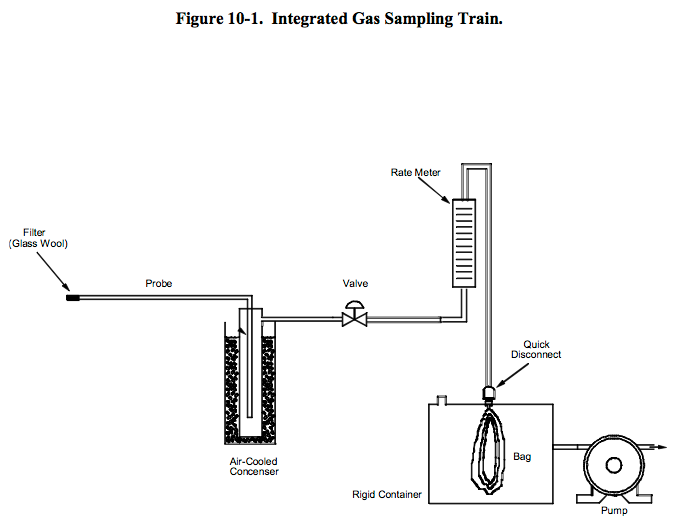
6.2 Integrated Sampling.
6.2.1 Air-Cooled condenser or Equivalent.
To remove any excess moisture.
6.2.2 Valve.
Needle valve, or equivalent, to adjust flow rate.
6.2.3 pump.
Leak-free diaphragm type, or equivalent, to transport gas.
6.2.4 Rate Meter.
Rotameter, or equivalent, to measure a flow range from 0 to 1.0 liter per minute (0.035 cfm).
6.2.5 Flexible Bag.
tedlar, or equivalent, with a capacity of 60 to 90 liters (2 to 3 ft3).
Leak-test the bag in the laboratory before using by evacuating with a pump followed by a dry gas meter. When the evacuation is complete, there should be no flow through the meter.
6.3 What analyzer must I use?
You must use an instrument that continuously measures CO in the gas stream and meets the specifications in Section 13.0. The dual-range analyzer provisions in Section 6.2.8.1 of Method 7E apply.
7.0 Reagents and Standards
7.1 calibration Gas.
What calibration gases do I need?
Refer to Section 7.1 of Method 7E for the calibration gas requirements.
7.2 Interference Check.
What additional reagents do I need for the interference check?
Use the appropriate test gases listed in Table 7E-3 of Method 7E (i.e., potential interferents, as identified by the instrument manufacturer) to conduct the interference check.
8.0 Sample Collection, Preservation, Storage, and Transport Emission Test Procedure
8.1 Sampling Site and Sampling Points.
You must follow Section 8.1 of Method 7E.
8.2 Initial Measurement System Performance Tests.
You must follow the procedures in Section 8.2 of Method 7E. If a dilution-type measurement system is used, the special considerations in Section 8.3 of Method 7E also apply.
8.3 Interference Check.
You must follow the procedures of Section 8.2.7 of Method 7E.
8.4 Sample Collection.
8.4.1 Continuous Sampling.
You must follow the procedures of Section 8.4 of Method 7E.
8.4.2 Integrated Sampling.
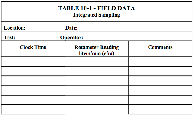
Evacuate the flexible bag. Set up the equipment as shown in Figure 10-1 with the bag disconnected. Place the Probe in the stack and purge the sampling line. Connect the bag, making sure that all connections are leak-free. Sample at a rate proportional to the stack velocity. If needed, the CO2 content of the gas may be determined by using the Method 3 integrated sample procedures, or by weighing an ascarite CO2 removal tube used and computing CO2 concentration from the gas volume sampled and the weight gain of the tube. Data may be recorded on a form similar to Table 10-1.
8.5 Post-Run System Bias Check, Drift Assessment, and Alternative Dynamic Spike Procedure.
You must follow the procedures in Sections 8.5 and 8.6 of Method 7E.
9.0 Quality Control
Follow the quality control procedures in Section 9.0 of Method 7E.
10.0 Calibration and Standardization
Follow the procedures for calibration and standardization in Section 10.0 of Method 7E
11.0 Analytical Procedures
Because sample collection and analysis are performed together (see Section 8), additional discussion of the analytical procedure is not necessary.
12.0 Calculations and Data Analysis
You must follow the procedures for calculations and data analysis in Section 12.0 of Method 7E, as applicable, substituting CO for NOx as applicable.
12.1 Concentration Correction for CO2 Removal.
Correct the CO concentration for CO2 removal (if applicable) using Eq. 10-1.
CAvg = CCOstack (1−FCO2)
Where:
| CAvg | = | Average gas concentration for the test run, ppm. |
| CCO stack | = | Average unadjusted stack gas CO concentration indicated by the data recorder for the test run, ppmv. |
| FCO2 | = | Volume fraction of CO2 in the sample, i.e., percent CO2 from Orsat analysis divided by 100. |
13.0 Method Performance
The specifications for analyzer calibration error, system bias, drift, interference check, and alternative dynamic spike procedure are the same as in Section 13.0 of Method 7E.
14.0 Pollution Prevention [Reserved]
15.0 Waste Management [Reserved]
16.0 Alternative Procedures
The dynamic spike procedure and the manufacturer stability test are the same as in Sections 16.1 and 16.3 of Method 7E
17.0 References
1. “EPA Traceability Protocol for Assay and Certification of Gaseous calibration Standards” September 1997 as amended, EPA-600/R-97/121
18.0 Tables, Diagrams, flowcharts, and Validation Data
- Analytical
- Ion Chromatography
- Gas Chromatography
- Gravimetrics
- Ash Resistivity
- Inks/Coatings
- Scrubber Stoichiometry
- Titrations
- Mercury Sorbent Trap
- Engineering
- Express Products
- Rental Instruments
- MET80 Mercury Monitor
- Continuous Emission Monitors
- Gas Sampling Equipment
- Mobile Power Supply
Our Resources
- Technical Resources