- Home
- Careers
- Contact
- About
-
Who we are and what we do. -
Press releases, announcements, and notable corporate information. -
We are looking for a few A people. -
We have over 40 years of innovation to create value for our customers. -
We aim to be the highest value provider of every product and service we offer. -
An easy guide to Probe fundamentals.
-
- Services
-
In additional to the analytical results we normally include an expert analysts summary.
We use our decades of experience to help you better understand your data. -
CleanAir can insures that the project goals and testing are objectives are met.
-
We can ship what you need today. It will work. You get a company of experts when you rent from CleanAir. - Thermal Performance
-
- Rental
-
Our factory reconditioning experts work to make old as good as new. -
CleanAir can provide the services required to care of your emissions measurement or power measurement instruments, no matter the age, model or manufacturer.
-
We deliver rental, emergency, or supplemental instruments and onsite services quickly, with minimal operational interruptions .
-
- Products
Featured Product

UL Listed Mobile Temporary Power
Look professional. Don't risk a OSHA fine, or worse causing your customer to get an OSHA or MSHA fine by using an unsafe mobile power distribution system. The CleanAir Temporary Power cart is UL listed! Read more... -
Reference
-
Overviews of products and services -
Learn about our companies and business -
Detailed technical information about the functioning of our products -
Guides and instructions on proper installation and service -
Guides and instructions on proper installation and service -
Drawings, configuration, materials, and limits useful for the planning and layout.
-
CleanAir's reference of video content -
Publications addressing an issue or topic
-
- Site Map
 Express
 FTIR
FTIR Mercury
 Emission Sampling Equipment
 Instrument Rental
EPA Methods List with Links
US EPA Method 29 - DETERMINATION OF METALS EMISSIONS FROM STATIONARY SOURCES
NOTE: This method does not include all of the specifications (e.g. equipment and supplies) and procedures (e.g., sampling and analytical) essential to its performance. Some material is incorporated by reference from other methods in this part. Therefore, to obtain reliable results, persons using this method should have a thorough knowledge of at least the following additional test methods: Method 5 and Method 12.
Content [ show/hide ].1.0 Scope and Application.
1.1 Analytes.
Analyte CAS No.
Antimony (Sb) 7440-36-0
Arsenic (As) 7440-38-2
Barium (Ba) 7440-39-3
Beryllium (Be) 7440-41-7
Cadmium (Cd) 7440-43-9
Chromium (Cr) 7440-47-3
Cobalt (Co) 7440-48-4
Copper (Cu) 7440-50-8
Lead (Pb) 7439-92-1
Manganese (Mn) 7439-96-5
Mercury (Hg) 7439-97-6
Nickel (Ni) 7440-02-0
Phosphorus (P) 7723-14-0
Selenium (Se) 7782-49-2
Silver (Ag) 7440-22-4
Thallium (Tl) 7440-28-0
Zinc (Zn) 7440-66-6
1.2 Applicability.
This method is applicable to the determination of metals emissions from stationary sources. This method may be used to determine particulate emissions in addition to the metals emissions if the prescribed procedures and precautions are followed.
1.2.1 Hg emissions can be measured, alternatively, using EPA Method 101A of Appendix B, 40 CFR Part 61. Method 101-A measures only Hg but it can be of special interest to sources which need to measure both Hg and Mn emissions.
2.0 Summary of Method.
2.1 Principle.
A stack sample is withdrawn isokinetically from the source, particulate emissions are collected in the Probe and on a heated filter, and gaseous emissions are then collected in an aqueous acidic solution of hydrogen peroxide (analyzed for all metals including Hg) and an aqueous acidic solution of potassium permanganate (analyzed only for Hg). The recovered samples are digested, and appropriate fractions are analyzed for Hg by cold vapor atomic absorption spectroscopy (CVAAS) and for Sb, As, Ba, Be, Cd, Cr, Co, Cu, Pb, Mn, Ni, P, Se, Ag, Tl, and Zn by inductively coupled argon plasma emission spectroscopy (ICAP) or atomic absorption spectroscopy (AAS). Graphite furnace atomic absorption spectroscopy (GFAAS) is used for analysis of Sb, As, Cd, Co, Pb, Se, and Tl if these elements require greater analytical sensitivity than can be obtained by ICAP. If one so chooses, AAS may be used for analysis of all listed metals if the resulting in-stack method detection limits meet the goal of the testing program. Similarly, inductively coupled plasma-mass spectroscopy (ICP-MS) may be used for analysis of Sb, As, Ba, Be, Cd, Cr, Co, Cu, Pb, Mn, Ni, Ag, Tl and Zn.
3.0 Definitions. [Reserved]
4.0 Interferences.
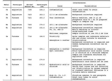
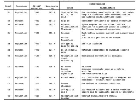
4.1 Iron (Fe) can be a spectral interference during the analysis of As, Cr, and Cd by ICAP. Aluminum (Al) can be a spectral interference during the analysis of As and Pb by ICAP. Generally, these interferences can be reduced by diluting the analytical sample, but such dilution raises the in-stack detection limits. Background and overlap corrections may be used to adjust for spectral interferences. Refer to Method 6010 of Reference 2 in Section 16.0 or the other analytical methods used for details on potential interferences to this method. For all GFAAS analyses, use matrix modifiers to limit interferences, and matrix match all standards.
5.0 Safety.
5.1 Disclaimer.
This method may involve hazardous materials, operations, and equipment. This test method may not address all of the safety problems associated with its use. It is the responsibility of the user of this test method to establish appropriate safety and health practices and to determine the applicability of regulatory limitations prior to performing this test method.
5.2 Corrosive Reagents.
The following reagents are hazardous. Personal protective equipment and safe procedures are useful in preventing chemical splashes. If contact occurs, immediately flush with copious amounts of water at least 15 minutes. Remove clothing under shower and decontaminate. Treat residual chemical burn as thermal burn.
5.2.1 Nitric Acid (HNO3). Highly corrosive to eyes, skin, nose, and lungs. Vapors cause bronchitis, pneumonia, or edema of lungs. Reaction to inhalation may be delayed as long as 30 hours and still be fatal. Provide ventilation to limit exposure. Strong oxidizer. Hazardous reaction may occur with organic materials such as solvents.
5.2.2 Sulfuric Acid (H2SO4). Rapidly destructive to body tissue. Will cause third degree burns. Eye damage may result in blindness. Inhalation may be fatal from spasm of the larynx, usually within 30 minutes. May cause lung tissue damage with edema. 1 mg/m>3 for 8 hours will cause lung damage or, in higher concentrations, death. Provide ventilation to limit inhalation. Reacts violently with metals and organics.
5.2.3 Hydrochloric Acid (HCl). Highly corrosive liquid with toxic vapors. Vapors are highly irritating to eyes, skin, nose, and lungs, causing severe damage. May cause bronchitis, pneumonia, or edema of lungs. Exposure to concentrations of 0.13 to 0.2 percent can be lethal to humans in a few minutes. Provide ventilation to limit exposure. Reacts with metals, producing hydrogen gas.
5.2.4 Hydrofluoric Acid (HF). Highly corrosive to eyes, skin, nose, throat, and lungs. Reaction to exposure may be delayed by 24 hours or more. Provide ventilation to limit exposure.
5.2.5 Hydrogen Peroxide (H2O2). Irritating to eyes, skin, nose, and lungs. 30% H2O2is a strong oxidizing agent. Avoid contact with skin, eyes, and combustible material. Wear gloves when handling.
5.2.6 Potassium Permanganate (KMnO4). Caustic, strong oxidizer. Avoid bodily contact with.
5.2.7 Potassium Persulfate. Strong oxidizer. Avoid bodily contact with. Keep containers well closed and in a cool place.
5.3 Reaction Pressure.
Due to the potential reaction of the potassium permanganate with the acid, there could be pressure buildup in the acidic KMnO4 absorbing solution storage bottle. Therefore these bottles shall not be fully filled and shall be vented to relieve excess pressure and prevent explosion potentials. Venting is required, but not in a manner that will allow contamination of the solution. A No. 70-72 hole drilled in the container cap and Teflon liner has been used.
6.0 Equipment and Supplies.
6.1 Sampling.
A schematic of the sampling train is shown in Figure 29-1. It has general similarities to the Method 5 train.
6.1.1 Probe probe nozzle (Probe Tip) and Borosilicate or Quartz glass Probe Liner. Same as Method 5, Sections
6.1.1.1 and 6.1.1.2, except that glass probe nozzles are required unless alternate tips are constructed of materials that are free from contamination and will not interfere with the sample. If a Probe tip other than glass is used, no correction to the sample test results to compensate for the probe nozzle's effect on the sample is allowed. Probe fittings of plastic such as Teflon, polypropylene, etc. are recommended instead of metal fittings to prevent contamination. If one chooses to do so, a single glass piece consisting of a combined Probe tip and Probe liner may be used.
6.1.2 pitot Tube and Differential Pressure Gauge. Same as Method 2, Sections 6.1 and 6.2, respectively.
6.1.3 filter Holder. glass, same as Method 5, Section 6.1.1.5, except use a Teflon filter support or other non-metallic, non-contaminating support in place of the glass frit.
6.1.4 filter Heating System. Same as Method 5, Section 6.1.1.6.
6.1.5 condenser. Use the following system for condensing and collecting gaseous metals and determining the moisture content of the stack gas. The condensing system shall consist of four to seven impingers connected in series with leak-free ground glass fittings or other leak-free, non-contaminating fittings. Use the first impinger as a moisture trap. The second impinger (which is the first HNO3/H2O2 impinger) shall be identical to the first impinger in Method 5. The third impinger (which is the second HNO3/H2O2 impinger) shall be a Greenburg Smith impinger with the standard tip as described for the second impinger in Method 5, Section 6.1.1.8. The fourth (empty) impinger and the fifth and sixth (both acidified KMnO4) impingers are the same as the first impinger in Method 5. Place a tenperature sensor capable of measuring to within 1C (2F) at the outlet of the last impinger. If no Hg analysis is planned, then the fourth, fifth, and sixth impingers are not used.
6.1.6 metering System, barometer, and Gas Density Determination equipment. Same as Method 5, Sections 6.1.1.9, 6.1.2, and 6.1.3, respectively.
6.1.7 Teflon Tape. For capping openings and sealing connections, if necessary, on the sampling train.
6.2 Sample Recovery.
Same as Method 5, Sections 6.2.1 through 6.2.8 (Probe-Liner and Probe-probe nozzle Brushes or Swabs, Wash Bottles, Sample Storage Containers, Petri Dishes, glass Graduated Cylinder, Plastic Storage Containers, Funnel and Rubber Policeman, and glass Funnel), respectively, with the following exceptions and additions:
6.2.1 Non-metallic Probe-Liner and Probe-probe nozzle Brushes or Swabs. Use non-metallic Probe-liner and Probe probe nozzle brushes or swabs for quantitative recovery of materials collected in the front-half of the sampling train.
6.2.2 Sample Storage Containers. Use glass bottles (see Section 8.1 of this Method) with Teflon-lined caps that are non-reactive to the oxidizing solutions, with capacities of 1000- and 500-ml, for storage of acidified KMnO4- containing samples and blanks. glass or polyethylene bottles may be used for other sample types.
6.2.3 Graduated Cylinder. glass or equivalent.
6.2.4 Funnel. glass or equivalent.
6.2.5 Labels. For identifying samples.
6.2.6 Polypropylene Tweezers and/or Plastic Gloves. For recovery of the filter from the sampling train filter holder.
6.3 Sample Preparation and Analysis.
6.3.1 Volumetric Flasks, 100-ml, 250-ml, and 1000-ml. For preparation of standards and sample dilutions.
6.3.2 Graduated Cylinders. For preparation of reagents.
6.3.3 Parr Bombs or Microwave Pressure Relief Vessels with Capping Station (CEM Corporation model or equivalent). For sample digestion.
6.3.4 Beakers and Watch glasses. 250-ml beakers, with watch glass covers, for sample digestion.
6.3.5 Ring Stands and Clamps. For securing equipment such as filtration apparatus.
6.3.6 filter Funnels. For holding filter paper.
6.3.7 Disposable Pasteur Pipets and Bulbs.
6.3.8 Volumetric Pipets.
6.3.9 Analytical Balance. Accurate to within 0.1 mg.
6.3.10 Microwave or Conventional oven. For heating samples at fixed power levels or temperatures, respectively.
6.3.11 Hot Plates.
6.3.12 Atomic Absorption Spectrometer (AAS). Equipped with a background corrector.
6.3.12.1 Graphite Furnace Attachment. With Sb, As, Cd, Co, Pb, Se, and Tl hollow cathode lamps (HCLs) or electrodeless discharge lamps (EDLs). Same as Reference 2 in Section 16.0. Methods 7041 (Sb), 7060 (As), 7131 (Cd), 7201 (Co), 7421 (Pb), 7740 (Se), and 7841 (Tl).
6.3.12.2 Cold Vapor Mercury Attachment. With a mercury HCL or EDL, an air recirculation pump, a quartz cell, an aerator apparatus, and a heat lamp or desiccator tube. The heat lamp shall be capable of raising the temperature at the quartz cell by 1OC above ambient, so that no condensation forms on the wall of the quartz cell. Same as Method 7470 in Reference 2 in Section 16.0. See NOTE 2: Section 11.1.3 for other acceptable approaches for analysis of Hg in which analytical detection limits of 0.002 ng/ml were obtained.
6.3.13 Inductively Coupled Argon Plasma Spectrometer. With either a direct or sequential reader and an alumina torch. Same as EPA Method 6010 in Reference 2 in Section 16.0.
6.3.14 Inductively Coupled Plasma-Mass Spectrometer. Same as EPA Method 6020 in Reference 2 in Section 16.0.
7.0 Reagents and Standards.
7.1 Conform to the Specifications
Unless otherwise indicated, it is intended that all reagents conform to the specifications established by the Committee on Analytical Reagents of the American Chemical Society, where such specifications are available. Otherwise, use the best available grade.
7.2 Sampling Reagents.
7.2.1 Sample filters. Without organic binders. The filters shall contain less than 1.3 g/in.2 of each of the metals to be measured. Analytical results provided by filter manufacturers stating metals content of the filters are acceptable. However, if no such results are available, analyze filter blanks for each target metal prior to emission testing. Quartz fiber filters meeting these requirements are recommended. However, if glass fiber filters become available which meet these requirements, they may be used. filter efficiencies and unreactiveness to sulfur dioxide (SO2) or sulfur trioxide (SO3) shall be as described in Section 7.1.1 of Method 5.
7.2.2 Water. To conform to ASTM Specification D1193-77 or 91, Type II (incorporated by reference -- see 60.17). If necessary, analyze the water for all target metals prior to field use. All target metals should be less than 1 ng/ml.
7.2.3 HNO3, Concentrated. Baker Instra-analyzed or equivalent.
7.2.4 HCl, Concentrated. Baker Instra-analyzed or equivalent.
7.2.5 H2O2, 30 Percent (V/V).
7.2.6 KMnO4.
7.2.7 H2SO4, Concentrated.
7.2.8 Silica Gel and Crushed Ice. Same as Method 5, Sections 7.1.2 and 7.1.4, respectively.
7.3 Pretest Preparation of Sampling Reagents.
7.3.1 HNO3/H2O2 Absorbing Solution, 5 Percent HNO3/10 Percent H2O2. Add carefully with stirring 50 ml of concentrated HNO3 to a 1000-ml volumetric flask containing approximately 500 ml of water, and then add carefully with stirring 333 ml of 30 percent H2O2. Dilute to volume with water. Mix well. This reagent shall contain less than 2 ng/ml of each target metal.
7.3.2 Acidic KMnO4 Absorbing Solution, 4 Percent KMnO4 (W/V), 10 Percent H2SO4 (V/V). Prepare fresh daily. Mix carefully, with stirring, 100 ml of concentrated H2SO4 into approximately 800 ml of water, and add water with stirring to make a volume of 1 liter: this solution is 10 percent H2SO4 (V/V). Dissolve, with stirring, 40 g of KMnO4 into 10 percent H2SO4 (V/V) and add 10 percent H2SO4 (V/V) with stirring to make a volume of 1 liter. Prepare and store in glass bottles to prevent degradation. This reagent shall contain less than 2 ng/ml of Hg.
Precaution: To prevent autocatalytic decomposition of the permanganate solution, filter the solution through Whatman 541 filter paper.
7.3.3 HNO3, 0.1 N. Add with stirring 6.3 ml of concentrated HNO3 (70 percent) to a flask containing approximately 900 ml of water. Dilute to 1000 ml with water. Mix well. This reagent shall contain less than 2 ng/ml of each target metal.
7.3.4 HCl, 8 N. Carefully add with stirring 690 ml of concentrated HCl to a flask containing 250 ml of water. Dilute to 1000 ml with water. Mix well. This reagent shall contain less than 2 ng/ml of Hg.
7.4 glassware Cleaning Reagents.
7.4.1 HNO3, Concentrated. Fisher ACS grade or equivalent.
7.4.2 Water. To conform to ASTM Specifications D1193, Type II.
7.4.3 HNO3, 10 Percent (V/V). Add with stirring 500 ml of concentrated HNO3 to a flask containing approximately 4000 ml of water. Dilute to 5000 ml with water. Mix well. This reagent shall contain less than 2 ng/ml of each target metal.
7.5 Sample Digestion and Analysis Reagents.
The metals standards, except Hg, may also be made from solid chemicals as described in Reference 3 in Section 16.0. Refer to References 1, 2, or 5 in Section 16.0 for additional information on Hg standards. The 1000 g/ml Hg stock solution standard may be made according to Section 7.2.7 of Method 101A.
7.5.1 HCl, Concentrated.
7.5.2 HF, Concentrated.
7.5.3 HNO3, Concentrated. Baker Instra-analyzed or equivalent.
7.5.4 HNO3, 50 Percent (V/V). Add with stirring 125 ml of concentrated HNO3 to 100 ml of water. Dilute to 250 ml with water. Mix well. This reagent shall contain less than 2 ng/ml of each target metal.
7.5.5 HNO3, 5 Percent (V/V). Add with stirring 50 ml of concentrated HNO3 to 800 ml of water. Dilute to 1000 ml with water. Mix well. This reagent shall contain less than 2 ng/ml of each target metal.
7.5.6 Water. To conform to ASTM Specifications D1193, Type II.
7.5.7 Hydroxylamine Hydrochloride and Sodium Chloride Solution. See Reference 2 In Section 16.0 for preparation.
7.5.8 Stannous Chloride. See Reference 2 in Section 16.0 for preparation.
7.5.9 KMnO4, 5 Percent (W/V). See Reference 2 in Section 16.0 for preparation.
7.5.10 H2SO4, Concentrated.
7.5.11 Potassium Persulfate, 5 Percent (W/V). See Reference 2 in Section 16.0 for preparation.
7.5.12 Nickel Nitrate, Ni(N03)2 .6H20.
7.5.13 Lanthanum Oxide, La203.
7.5.14 Hg Standard (AAS Grade), 1000 g/ml.
7.5.15 Pb Standard (AAS Grade), 1000 g/ml.
7.5.16 As Standard (AAS Grade), 1000 g/ml.
7.5.17 Cd Standard (AAS Grade), 1000 g/ml.
7.5.18 Cr Standard (AAS Grade), 1000 g/ml.
7.5.19 Sb Standard (AAS Grade), 1000 g/ml.
7.5.20 Ba Standard (AAS Grade), 1000 g/ml.
7.5.21 Be Standard (AAS Grade), 1000 g/ml.
7.5.22 Co Standard (AAS Grade), 1000 g/ml.
7.5.23 Cu Standard (AAS Grade), 1000 g/ml.
7.5.24 Mn Standard (AAS Grade), 1000 g/ml.
7.5.25 Ni Standard (AAS Grade), 1000 g/ml.
7.5.26 P Standard (AAS Grade), 1000 g/ml.
7.5.27 Se Standard (AAS Grade), 1000 g/ml.
7.5.28 Ag Standard (AAS Grade), 1000 g/ml.
7.5.29 Tl Standard (AAS Grade), 1000 g/ml.
7.5.30 Zn Standard (AAS Grade), 1000 g/ml.
7.5.31 Al Standard (AAS Grade), 1000 g/ml.
7.5.32 Fe Standard (AAS Grade), 1000 g/ml.
7.5.33 Hg Standards and Quality Control Samples. Prepare fresh weekly a 10 g/ml intermediate Hg standard by adding 5 ml of 1000 g/ml Hg stock solution prepared according to Method 101A to a 500-ml volumetric flask; dilute with stirring to 500 ml by first carefully adding 20 ml of 15 percent HNO3 and then adding water to the 500-ml volume. Mix well. Prepare a 200 ng/ml working Hg standard solution fresh daily: add 5 ml of the 10 g/ml intermediate standard to a 250-ml volumetric flask, and dilute to 250 ml with 5 ml of 4 percent KMnO4, 5 ml of 15 percent HNO>3, and then water. Mix well. Use at least five separate aliquots of the working Hg standard solution and a blank to prepare the standard curve. These aliquots and blank shall contain 0.0, 1.0, 2.0, 3.0, 4.0, and 5.0 ml of the working standard solution containing 0, 200, 400, 600, 800, and 1000 ng Hg, respectively. Prepare quality control samples by making a separate 10 g/ml standard and diluting until in the calibration range.
7.5.34 ICAP Standards and Quality Control Samples. calibration standards for ICAP analysis can be combined into four different mixed standard solutions as follows:
MIXED STANDARD SOLUTIONS FOR ICAP ANALYSIS
Solution Elements
I As, Be, Cd, Mn,
Pb, Se, Zn
II Ba, Co, Cu, Fe
III Al, Cr, Ni
IV Ag, P, Sb, Tl
Prepare these standards by combining and diluting the appropriate volumes of the 1000 g/ml solutions with 5 percent HNO3. A minimum of one standard and a blank can be used to form each calibration curve. However, prepare a separate quality control sample spiked with known amounts of the target metals in quantities in the mid-range of the calibration curve. Suggested standard levels are 25 g/ml for Al, Cr and Pb, 15 g/ml for Fe, and 10 g/ml for the remaining elements. Prepare any standards containing less than 1 g/ml of metal on a daily basis. Standards containing greater than 1 g/ml of metal should be stable for a minimum of 1 to 2 weeks. For ICP-MS, follow Method 6020 in EPA Publication SW-846 Third Edition (November 1986) including updates I, II, IIA, IIB and III, as incorporated by reference in 60.17(i).
7.5.35 GFAAS Standards. Sb, As, Cd, Co, Pb, Se, and Tl. Prepare a 10 g/ml standard by adding 1 ml of 1000 g/ml standard to a 100-ml volumetric flask. Dilute with stirring to 100 ml with 10 percent HNO3. For GFAAS, matrix match the standards. Prepare a 100 ng/ml standard by adding 1 ml of the 10 g/ml standard to a 100-ml volumetric flask, and dilute to 100 ml with the appropriate matrix solution. Prepare other standards by diluting the 100 ng/ml standards. Use at least five standards to make up the standard curve. Suggested levels are 0, 10, 50, 75, and 100 ng/ml. Prepare quality control samples by making a separate 10 g/ml standard and diluting until it is in the range of the samples. Prepare any standards containing less than 1 g/ml of metal on a daily basis. Standards containing greater than 1 g/ml of metal should be stable for a minimum of 1 to 2 weeks.
7.5.36 Matrix Modifiers.
7.5.36.1 Nickel Nitrate, 1 Percent (V/V). Dissolve 4.956 g of Ni(N03)26H20 or other nickel compound suitable for preparation of this matrix modifier in approximately 50 ml of water in a 100-ml volumetric flask. Dilute to 100 ml with water.
7.5.36.2 Nickel Nitrate, 0.1 Percent (V/V). Dilute 10 ml of 1 percent nickel nitrate solution to 100 ml with water. Inject an equal amount of sample and this modifier into the graphite furnace during GFAAS analysis for As.
7.5.36.3 Lanthanum. Carefully dissolve 0.5864 g of La203 in 10 ml of concentrated HN03, and dilute the solution by adding it with stirring to approximately 50 ml of water. Dilute to 100 ml with water, and mix well. Inject an equal amount of sample and this modifier into the graphite furnace during GFAAS analysis for Pb.
7.5.37 Whatman 40 and 541 filter Papers (or equivalent). For filtration of digested samples.
8.0 Sample Collection, Preservation, Transport, and Storage.
8.1 Sampling.
The complexity of this method is such that, to obtain reliable results, both testers and analysts must be trained and experienced with the test procedures, including source sampling; reagent preparation and handling; sample handling; safety equipment and procedures; analytical calculations; reporting; and the specific procedural descriptions throughout this method.
8.1.1 Pretest Preparation. Follow the same general procedure given in Method 5, Section 8.1, except that, unless particulate emissions are to be determined, the filter need not be desiccated or weighed. First, rinse all sampling train glassware with hot tap water and then wash in hot soapy water. Next, rinse glassware three times with tap water, followed by three additional rinses with water. Then soak all glassware in a 10 percent (V/V) nitric acid solution for a minimum of 4 hours, rinse three times with water, rinse a final time with acetone, and allow to air dry. Cover all glassware openings where contamination can occur until the sampling train is assembled for sampling.
8.1.2 Preliminary Determinations. Same as Method 5, Section 8.1.2.
8.1.3 Preparation of Sampling Train.
8.1.3.1 Set up the sampling train as shown in Figure 29-1. Follow the same general procedures given in Method 5, Section 8.3, except place 100 ml of the HNO3/H2O2 solution (Section 7.3.1 of this method) in each of the second and third impingers as shown in Figure 29-1. Place 100 ml of the acidic KMnO4 absorbing solution (Section 7.3.2 of this method) in each of the fifth and sixth impingers as shown in Figure 29-1, and transfer approximately 200 to 300 g of preweighed silica gel from its container to the last impinger. Alternatively, the silica gel may be weighed directly in the impinger just prior to final train assembly.
8.1.3.2 Based on the specific source sampling conditions, the use of an empty first impinger can be eliminated if the moisture to be collected in the impingers will be less than approximately 100 ml.
8.1.3.3 If Hg analysis will not be performed, the fourth, fifth, and sixth impingers as shown in Figure 29-1 are not required.
8.1.3.4 To insure leak-free sampling train connections and to prevent possible sample contamination problems, use Teflon tape or other non-contaminating material instead of silicone grease.
Precaution: Exercise extreme care to prevent contamination within the train. Prevent the acidic KMnO4 from contacting any glassware that contains sample material to be analyzed for Mn. Prevent acidic H2O2from mixing with the acidic KMnO4.
8.1.4 Leak-Check Procedures. Follow the leak-check procedures given in Method 5, Section 8.4.2 (Pretest Leak-Check), Section 8.4.3 (Leak-Checks During the Sample Run), and Section 8.4.4 (Post-Test Leak-Checks).
8.1.5 Sampling Train Operation. Follow the procedures given in Method 5, Section 8.5. When sampling for Hg, use a procedure analogous to that described in Section 8.1 of Method 101A, 40 CFR Part 61, Appendix B, if necessary to maintain the desired color in the last acidified permanganate impinger. For each run, record the data required on a data sheet such as the one shown in Figure 5-3 of Method 5.
8.1.6 Calculation of Percent Isokinetic. Same as Method 5, Section 12.11.
8.2 Sample Recovery.
8.2.1 Begin cleanup procedures as soon as the Probe is removed from the stack at the end of a sampling period. The Probe should be allowed to cool prior to sample recovery. When it can be safely handled, wipe off all external particulate matter near the tip of the Probe probe nozzle and place a rinsed, non-contaminating cap over the Probe probe nozzle to prevent losing or gaining particulate matter. Do not cap the Probe tip tightly while the sampling train is cooling; a vacuum can form in the filter holder with the undesired result of drawing liquid from the impingers onto the filter.
8.2.2 Before moving the sampling train to the cleanup site, remove the Probe from the sampling train and cap the open outlet. Be careful not to lose any condensate that might be present. Cap the filter inlet where the Probe was fastened. Remove the umbilical cord from the last impinger and cap the impinger. Cap the filter holder outlet and impinger inlet. Use non-contaminating caps, whether ground glass stoppers, plastic caps, serum caps, or Teflon tape to close these openings.
8.2.3 Alternatively, the following procedure may be used to disassemble the train before the Probe and filter holder/oven are completely cooled: Initially disconnect the filter holder outlet/impinger inlet and loosely cap the open ends. Then disconnect the Probe from the filter holder or cyclone inlet and loosely cap the open ends. Cap the Probe tip and remove the umbilical cord as previously described.
8.2.4 Transfer the Probe and filter-impinger assembly to a cleanup area that is clean and protected from the wind and other potential causes of contamination or loss of sample. Inspect the train before and during disassembly and note any abnormal conditions. Take special precautions to assure that all the items necessary for recovery do not contaminate the samples. The sample is recovered and treated as follows (see schematic in Figures 29-2a and 29-2b):
8.2.5 Container No. 1 (Sample filter). Carefully remove the filter from the filter holder and place it in its labeled Petri dish container. To handle the filter, use either acid-washed polypropylene or Teflon coated tweezers or clean, disposable surgical gloves rinsed with water and dried. If it is necessary to fold the filter, make certain the particulate cake is inside the fold. Carefully transfer the filter and any particulate matter or filter fibers that adhere to the filter holder gasket to the Petri dish by using a dry (acid-cleaned) nylon bristle brush. Do not use any metal-containing materials when recovering this train. Seal the labeled Petri dish.
8.2.6 Container No. 2 (Acetone Rinse). Perform this procedure only if a determination of particulate emissions is to be made. Quantitatively recover particulate matter and any condensate from the Probe probe nozzle, Probe fitting, Probe liner, and front half of the filter holder by washing these components with a total of 100 ml of acetone, while simultaneously taking great care to see that no dust on the outside of the Probe or other surfaces gets in the sample. The use of exactly 100 ml is necessary for the subsequent blank correction procedures. Distilled water may be used instead of acetone when approved by the Administrator and shall be used when specified by the Administrator; in these cases, save a water blank and follow the Administrator's directions on analysis.
8.2.6.1 Carefully remove the Probe probe nozzle, and clean the inside surface by rinsing with acetone from a wash bottle while brushing with a non-metallic brush. Brush until the acetone rinse shows no visible particles, then make a final rinse of the inside surface with acetone.
8.2.6.2 Brush and rinse the sample exposed inside parts of the Probe fitting with acetone in a similar way until no visible particles remain. Rinse the Probe liner with acetone by tilting and rotating the Probe while squirting acetone into its upper end so that all inside surfaces will be wetted with acetone. Allow the acetone to drain from the lower end into the sample container. A funnel may be used to aid in transferring liquid washings to the container. Follow the acetone rinse with a non-metallic Probe brush. Hold the Probe in an inclined position, squirt acetone into the upper end as the Probe brush is being pushed with a twisting action three times through the Probe. Hold a sample container underneath the lower end of the Probe, and catch any acetone and particulate matter which is brushed through the Probe until no visible particulate matter is carried out with the acetone or until none remains in the Probe liner on visual inspection. Rinse the brush with acetone, and quantitatively collect these washings in the sample container. After the brushing, make a final acetone rinse of the Probe as described above.
8.2.6.3 It is recommended that two people clean the Probe to minimize sample losses. Between sampling runs, keep brushes clean and protected from contamination. Clean the inside of the front-half of the filter holder by rubbing the surfaces with a non-metallic brush and rinsing with acetone. Rinse each surface three times or more if needed to remove visible particulate. Make a final rinse of the brush and filter holder. After all acetone washings and particulate matter have been collected in the sample container, tighten the lid so that acetone will not leak out when shipped to the laboratory. Mark the height of the fluid level to determine whether or not leakage occurred during transport. Clearly label the container to identify its contents.
8.2.7 Container No. 3 (Probe Rinse). Keep the Probe assembly clean and free from contamination during the Probe rinse. Rinse the Probe probe nozzle and fitting, Probe liner, and front-half of the filter holder thoroughly with a total of 100 ml of 0.1 N HNO3, and place the wash into a sample storage container. Perform the rinses as applicable and generally as described in Method 12, Section 8.7.1. Record the volume of the rinses. Mark the height of the fluid level on the outside of the storage container and use this mark to determine if leakage occurs during transport. Seal the container, and clearly label the contents. Finally, rinse the probe nozzle, Probe liner, and front-half of the filter holder with water followed by acetone, and discard these rinses.
NOTE: The use of a total of exactly 100 ml is necessary for the subsequent blank correction procedures.
8.2.8 Container No. 4 (impingers 1 through 3, Moisture Knockout impinger, when used, HNO3/H2O2impingers Contents and Rinses). Due to the potentially large quantity of liquid involved, the tester may place the impinger solutions from impingers 1 through 3 in more than one container, if necessary. Measure the liquid in the first three impingers to within 0.5 ml using a graduated cylinder. Record the volume. This information is required to calculate the moisture content of the sampled flue gas. Clean each of the first three impingers, the filter support, the back half of the filter housing, and connecting glassware by thoroughly rinsing with 100 ml of 0.1 N HNO3 using the procedure as applicable in Method 12, Section 8.7.3.
NOTE: The use of exactly 100 ml of 0.1 N HNO>3 rinse is necessary for the subsequent blank correction procedures. Combine the rinses and impinger solutions, measure and record the final total volume. Mark the height of the fluid level, seal the container, and clearly label the contents.
8.2.9 Container Nos. 5A (0.1 N HNO3), 5B (KMnO4/H2SO4 absorbing solution), and 5C (8 N HCl rinse and dilution).
8.2.9.1 When sampling for Hg, pour all the liquid from the impinger (normally impinger No. 4) that immediately preceded the two permanganate impingers into a graduated cylinder and measure the volume to within 0.5 ml. This information is required to calculate the moisture content of the sampled flue gas. Place the liquid in Container No. 5A. Rinse the impinger with exactly 100 ml of 0.1 N HNO3 and place this rinse in Container No. 5A.
8.2.9.2 Pour all the liquid from the two permanganate impingers into a graduated cylinder and measure the volume to within 0.5 ml. This information is required to calculate the moisture content of the sampled flue gas. Place this acidic KMnO4 solution into Container No. 5B. Using a total of exactly 100 ml of fresh acidified KMnO4 solution for all rinses (approximately 33 ml per rinse), rinse the two permanganate impingers and connecting glassware a minimum of three times. Pour the rinses into Container No. 5B, carefully assuring transfer of all loose precipitated materials from the two impingers. Similarly, using 100 ml total of water, rinse the permanganate impingers and connecting glass a minimum of three times, and pour the rinses into Container 5B, carefully assuring transfer of any loose precipitated material. Mark the height of the fluid level, and clearly label the contents. Read the Precaution: in Section 7.3.2.
NOTE: Due to the potential reaction of KMnO>4 with acid, pressure buildup can occur in the sample storage bottles. Do not fill these bottles completely and take precautions to relieve excess pressure. A No. 70-72 hole drilled in the container cap and Teflon liner has been used successfully.
8.2.9.3 If no visible deposits remain after the water rinse, no further rinse is necessary. However, if deposits remain on the impinger surfaces, wash them with 25 ml of 8 N HCl, and place the wash in a separate sample container labeled No. 5C containing 200 ml of water. First, place 200 ml of water in the container. Then wash the impinger walls and stem with the HCl by turning the impinger on its side and rotating it so that the HCl contacts all inside surfaces. Use a total of only 25 ml of 8 N HCl for rinsing both permanganate impingers combined. Rinse the first impinger, then pour the actual rinse used for the first impinger into the second impinger for its rinse. Finally, pour the 25 ml of 8 N HCl rinse carefully into the container. Mark the height of the fluid level on the outside of the container to determine if leakage occurs during transport.
8.2.10 Container No. 6 (Silica Gel). Note the color of the indicating silica gel to determine whether it has been completely spent and make a notation of its condition. Transfer the silica gel from its impinger to its original container and seal it. The tester may use a funnel to pour the silica gel and a rubber policeman to remove the silica gel from the impinger. The small amount of particles that might adhere to the impinger wall need not be removed. Do not use water or other liquids to transfer the silica gel since weight gained in the silica gel impinger is used for moisture calculations. Alternatively, if a balance is available in the field, record the weight of the spent silica gel (or silica gel plus impinger) to the nearest 0.5 g.
8.2.11 Container No. 7 (Acetone Blank). If particulate emissions are to be determined, at least once during each field test, place a 100-ml portion of the acetone used in the sample recovery process into a container labeled No. 7. Seal the container.
8.2.12 Container No. 8A (0.1 N HNO3 Blank). At least once during each field test, place 300 ml of the 0.1 N HNO3solution used in the sample recovery process into a container labeled No. 8A. Seal the container.
8.2.13 Container No. 8B (Water Blank). At least once during each field test, place 100 ml of the water used in the sample recovery process into a container labeled No. 8B. Seal the container.
8.2.14 Container No. 9 (5 Percent HNO3/10 Percent H2O2 Blank). At least once during each field test, place 200 ml of the 5 Percent HNO3/10 Percent H2O2 solution used as the nitric acid impinger reagent into a container labeled No. 9. Seal the container.
8.2.15 Container No. 10 (Acidified KMnO4 Blank). At least once during each field test, place 100 ml of the acidified KMnO4 solution used as the impinger solution and in the sample recovery process into a container labeled No. 10. Prepare the container as described in Section 8.2.9.2. Read the Precaution: in Section 7.3.2 and read the NOTE in Section 8.2.9.2.
8.2.16 Container No. 11 (8 N HCl Blank). At least once during each field test, place 200 ml of water into a sample container labeled No. 11. Then carefully add with stirring 25 ml of 8 N HCl. Mix well and seal the container.
8.2.17 Container No. 12 (Sample filter Blank). Once during each field test, place into a Petri dish labeled No. 12 three unused blank filters from the same lot as the sampling filters. Seal the Petri dish.
8.3 Sample Preparation.
Note the level of the liquid in each of the containers and determine if any sample was lost during shipment. If a noticeable amount of leakage has occurred, either void the sample or use methods, subject to the approval of the Administrator, to correct the final results. A diagram illustrating sample preparation and analysis procedures for each of the sample train components is shown in Figure 29-3.
8.3.1 Container No. 1 (Sample filter).
8.3.1.1 If particulate emissions are being determined, first desiccate the filter and filter catch without added heat (do not heat the filters to speed the drying) and weigh to a constant weight as described in Section 11.2.1 of Method 5.
8.3.1.2 Following this procedure, or initially, if particulate emissions are not being determined in addition to metals analysis, divide the filter with its filter catch into portions containing approximately 0.5 g each. Place the pieces in the analyst's choice of either individual microwave pressure relief vessels or Parr Bombs. Add 6 ml of concentrated HNO3and 4 ml of concentrated HF to each vessel. For microwave heating, microwave the samples for approximately 12 to 15 minutes total heating time as follows: heat for 2 to 3 minutes, then turn off the microwave for 2 to 3 minutes, then heat for 2 to 3 minutes, etc., continue this alternation until the 12 to 15 minutes total heating time are completed (this procedure should comprise approximately 24 to 30 minutes at 600 watts). Microwave heating times are approximate and are dependent upon the number of samples being digested simultaneously. Sufficient heating is evidenced by sorbent reflux within the vessel. For conventional heating, heat the Parr Bombs at 140oC (285oF) for 6 hours. Then cool the samples to room temperature, and combine with the acid digested Probe rinse as required in Section 8.3.3.
8.3.1.3 If the sampling train includes an optional glass cyclone in front of the filter, prepare and digest the cyclone catch by the procedures described in Section 8.3.1.2 and then combine the digestate with the digested filter sample.
8.3.2 Container No. 2 (Acetone Rinse). Note the level of liquid in the container and confirm on the analysis sheet whether or not leakage occurred during transport. If a noticeable amount of leakage has occurred, either void the sample or use methods, subject to the approval of the Administrator, to correct the final results. Measure the liquid in this container either volumetrically within 1 ml or gravimetrically within 0.5 g. Transfer the contents to an acid-cleaned, tared 250-ml beaker and evaporate to dryness at ambient temperature and pressure. If particulate emissions are being determined, desiccate for 24 hours without added heat, weigh to a constant weight according to the procedures described in Section 11.2.1 of Method 5, and report the results to the nearest 0.1 mg. Redissolve the residue with 10 ml of concentrated HNO3. Quantitatively combine the resultant sample, including all liquid and any particulate matter, with Container No. 3 before beginning Section 8.3.3.
8.3.3 Container No. 3 (Probe Rinse). Verify that the pH of this sample is 2 or lower. If it is not, acidify the sample by careful addition with stirring of concentrated HNO3 to pH 2. Use water to rinse the sample into a beaker, and cover the beaker with a ribbed watch glass. Reduce the sample volume to approximately 20 ml by heating on a hot plate at a temperature just below boiling. Digest the sample in microwave vessels or Parr Bombs by quantitatively transferring the sample to the vessel or bomb, carefully adding the 6 ml of concentrated HNO3, 4 ml of concentrated HF, and then continuing to follow the procedures described in Section 8.3.1.2. Then combine the resultant sample directly with the acid digested portions of the filter prepared previously in Section 8.3.1.2. The resultant combined sample is referred to as "Sample Fraction 1". filter the combined sample using Whatman 541 filter paper. Dilute to 300 ml (or the appropriate volume for the expected metals concentration) with water. This diluted sample is "Analytical Fraction 1". Measure and record the volume of Analytical Fraction 1 to within 0.1 ml. Quantitatively remove a 50-ml aliquot and label as "Analytical Fraction 1B". Label the remaining 250-ml portion as "Analytical Fraction 1A". Analytical Fraction 1A is used for ICAP or AAS analysis for all desired metals except Hg. Analytical Fraction 1B is used for the determination of front-half Hg.
8.3.4 Container No. 4 (impingers 1-3). Measure and record the total volume of this sample to within 0.5 ml and label it "Sample Fraction 2". Remove a 75- to 100-ml aliquot for Hg analysis and label the aliquot "Analytical Fraction 2B". Label the remaining portion of Container No. 4 as "Sample Fraction 2A". Sample Fraction 2A defines the volume of Analytical Fraction 2A prior to digestion. All of Sample Fraction 2A is digested to produce "Analytical Fraction 2A". Analytical Fraction 2A defines the volume of Sample Fraction 2A after its digestion and the volume of Analytical Fraction 2A is normally 150 ml. Analytical Fraction 2A is analyzed for all metals except Hg. Verify that the pH of Sample Fraction 2A is 2 or lower. If necessary, use concentrated HNO3 by careful addition and stirring to lower Sample Fraction 2A to pH 2. Use water to rinse Sample Fraction 2A into a beaker and then cover the beaker with a ribbed watch glass. Reduce Sample Fraction 2A to approximately 20 ml by heating on a hot plate at a temperature just below boiling. Then follow either of the digestion procedures described in Sections 8.3.4.1 or 8.3.4.2.
8.3.4.1 Conventional Digestion Procedure. Add 30 ml of 50 percent HNO3, and heat for 30 minutes on a hot plate to just below boiling. Add 10 ml of 3 percent H2O2and heat for 10 more minutes. Add 50 ml of hot water, and heat the sample for an additional 20 minutes. Cool, filter the sample, and dilute to 150 ml (or the appropriate volume for the expected metals concentrations) with water. This dilution produces Analytical Fraction 2A. Measure and record the volume to within 0.1 ml.
8.3.4.2 Microwave Digestion Procedure. Add 10 ml of 50 percent HNO3 and heat for 6 minutes total heating time in alternations of 1 to 2 minutes at 600 Watts followed by 1 to 2 minutes with no power, etc., similar to the procedure described in Section 8.3.1. Allow the sample to cool. Add 10 ml of 3 percent H2O2 and heat for 2 more minutes. Add 50 ml of hot water, and heat for an additional 5 minutes. Cool, filter the sample, and dilute to 150 ml (or the appropriate volume for the expected metals concentrations) with water. This dilution produces Analytical Fraction 2A. Measure and record the volume to within 0.1 ml.
NOTE: All microwave heating times given are approximate and are dependent upon the number of samples being digested at a time. Heating times as given above have been found acceptable for simultaneous digestion of up to 12 individual samples. Sufficient heating is evidenced by solvent reflux within the vessel.
8.3.5 Container No. 5A (impinger 4), Container Nos. 5B and 5C (impingers 5 and 6). Keep the samples in Containers Nos. 5A, 5B, and 5C separate from each other. Measure and record the volume of 5A to within 0.5 ml. Label the contents of Container No. 5A to be Analytical Fraction 3A. To remove any brown MnO2 precipitate from the contents of Container No. 5B, filter its contents through Whatman 40 filter paper into a 500 ml volumetric flask and dilute to volume with water. Save the filter for digestion of the brown MnO2 precipitate. Label the 500 ml filtrate from Container No. 5B to be Analytical Fraction 3B. Analyze Analytical Fraction 3B for Hg within 48 hours of the filtration step. Place the saved filter, which was used to remove the brown MnO2 precipitate, into an appropriately sized vented container, which will allow release of any gases including chlorine formed when the filter is digested. In a laboratory hood which will remove any gas produced by the digestion of the MnO2, add 25 ml of 8 N HCl to the filter and allow to digest for a minimum of 24 hours at room temperature. filter the contents of Container No. 5C through a Whatman 40 filter into a 500-ml volumetric flask. Then filter the result of the digestion of the brown MnO2 from Container No. 5B through a Whatman 40 filter into the same 500-ml volumetric flask, and dilute and mix well to volume with water. Discard the Whatman 40 filter. Mark this combined 500-ml dilute HCl solution as Analytical Fraction 3C.
8.3.6 Container No. 6 (Silica Gel). Weigh the spent silica gel (or silica gel plus impinger) to the nearest 0.5 g using a balance.
9.0 Quality Control.
9.1 Field Reagent Blanks, if analyzed.
Perform the digestion and analysis of the blanks in Container Nos. 7 through 12 that were produced in Sections 8.2.11 through 8.2.17, respectively. For Hg field reagent blanks, use a 10 ml aliquot for digestion and analysis.
9.1.1 Digest and analyze one of the filters from Container No. 12 per Section 8.3.1, 100 ml from Container No. 7 per Section 8.3.2, and 100 ml from Container No. 8A per Section 8.3.3. This step produces blanks for Analytical Fractions 1A and 1B.
9.1.2 Combine 100 ml of Container No. 8A with 200 ml from Container No. 9, and digest and analyze the resultant volume per Section 8.3.4. This step produces blanks for Analytical Fractions 2A and 2B.
9.1.3 Digest and analyze a 100-ml portion of Container No. 8A to produce a blank for Analytical Fraction 3A. 9.1.4 Combine 100 ml from Container No. 10 with 33 ml from Container No. 8B to produce a blank for Analytical Fraction 3B. filter the resultant 133 ml as described for Container No. 5B in Section 8.3.5, except do not dilute the 133 ml. Analyze this blank for Hg within 48 hr of the filtration step, and use 400 ml as the blank volume when calculating the blank mass value. Use the actual volumes of the other analytical blanks when calculating their mass values.
9.1.5 Digest the filter that was used to remove any brown MnO2 precipitate from the blank for Analytical Fraction 3B by the same procedure as described in Section 8.3.5 for the similar sample filter. filter the digestate and the contents of Container No. 11 through Whatman 40 paper into a 500-ml volumetric flask, and dilute to volume with water. These steps produce a blank for Analytical Fraction 3C.
9.1.6 Analyze the blanks for Analytical Fraction Blanks 1A and 2A per Section 11.1.1 and/or Section 11.1.2. Analyze the blanks for Analytical Fractions 1B, 2B, 3A, 3B, and 3C per Section 11.1.3. Analysis of the blank for Analytical Fraction 1A produces the front-half reagent blank correction values for the desired metals except for Hg; Analysis of the blank for Analytical Fraction 1B produces the front-half reagent blank correction value for Hg. Analysis of the blank for Analytical Fraction 2A produces the back-half reagent blank correction values for all of the desired metals except for Hg, while separate analyses of the blanks for Analytical Fractions 2B, 3A, 3B, and 3C produce the back-half reagent blank correction value for Hg.
9.2 Quality Control Samples.
Analyze the following quality control samples.
9.2.1 ICAP and ICP-MS Analysis. Follow the respective quality control descriptions in Section 8 of Methods 6010 and 6020 in EPA Publication SW-846 Third Edition (November 1986) including updates I, II, IIA, IIB and III, as incorporated by reference in 60.17(i). For the purposes of a source test that consists of three sample runs, modify those requirements to include the following: two instrument check standard runs, two calibration blank runs, one interference check sample at the beginning of the analysis (analyze by Method of Standard Additions unless within 25 percent), one quality control sample to check the accuracy of the calibration standards (required to be within 25 percent of calibration), and one duplicate analysis (required to be within 20 percent of average or repeat all analyses).
9.2.2 Direct Aspiration AAS and/or GFAAS Analysis for Sb, As, Ba, Be, Cd, Cu, Cr, Co, Pb, Ni, Mn, Hg, P, Se, Ag, Tl, and Zn. Analyze all samples in duplicate. Perform a matrix spike on at least one front-half sample and one back-half sample, or one combined sample. If recoveries of less than 75 percent or greater than 125 percent are obtained for the matrix spike, analyze each sample by the Method of Standard Additions. Analyze a quality control sample to check the accuracy of the calibration standards. If the results are not within 20 percent, repeat the calibration.
9.2.3 CVAAS Analysis for Hg. Analyze all samples in duplicate. Analyze a quality control sample to check the accuracy of the calibration standards (if not within 15 percent, repeat calibration). Perform a matrix spike on one sample (if not within 25 percent, analyze all samples by the Method of Standard Additions). Additional information on quality control can be obtained from Method 7470 in EPA Publication SW-846 Third Edition (November 1986) including updates I, II, IIA, IIB and III, as incorporated by reference in 60.17(i),or in Standard Methods for Water and Wastewater Method 303F.
10.0 Calibration and Standardization.
NOTE: Maintain a laboratory log of all calibrations.
10.1 Sampling Train calibration.
Calibrate the sampling train components according to the indicated sections of Method 5: Probe probe nozzle (Section 10.1); pitot Tube (Section 10.2); metering System (Section 10.3); Probe Heater (Section 10.4); tenperature sensors (Section 10.5); Leak-Check of the metering System (Section 8.4.1); and barometer (Section 10.6).
10.2 Inductively Coupled Argon Plasma Spectrometer calibration.
Prepare standards as outlined in Section 7.5. Profile and calibrate the instrument according to the manufacturer's recommended procedures using those standards. Check the calibration once per hour. If the instrument does not reproduce the standard concentrations within 10 percent, perform the complete calibration procedures. Perform ICP-MS analysis by following Method 6020 in EPA Publication SW-846 Third Edition (November 1986) including updates I, II, IIA, IIB and III, as incorporated by reference in 60.17(i).
10.3 Atomic Absorption Spectrometer – Direct Aspiration AAS, GFAAS, and CVAAS analyses.
Prepare the standards as outlined in Section 7.5 and use them to calibrate the spectrometer. calibration procedures are also outlined in the EPA methods referred to in Table 29-2 and in Method 7470 in EPA Publication SW-846 Third Edition (November 1986) including updates I, II, IIA, IIB and III, as incorporated by reference in 60.17(i), or in Standard Methods for Water and Wastewater Method 303F (for Hg). Run each standard curve in duplicate and use the mean values to calculate the calibration line. Recalibrate the instrument approximately once every 10 to 12 samples.
11.0 Analytical Procedure.
11.1 Sample Analysis.
For each sampling train sample run, seven individual analytical samples are generated; two for all desired metals except Hg, and five for Hg. A schematic identifying each sample container and the prescribed analytical preparation and analysis scheme is shown in Figure 29-3. The first two analytical samples, labeled Analytical Fractions 1A and 1B, consist of the digested samples from the front-half of the train. Analytical Fraction 1A is for ICAP, ICP-MS or AAS analysis as described in Sections 11.1.1 and 11.1.2, respectively. Analytical Fraction 1B is for front-half Hg analysis as described in Section 11.1.3. The contents of the back half of the train are used to prepare the third through seventh analytical samples. The third and fourth analytical samples, labeled Analytical Fractions 2A and 2B, contain the samples from the moisture removal impinger No. 1, if used, and HNO3/H2O2 impingers Nos. 2 and 3. Analytical Fraction 2A is for ICAP, ICP-MS or AAS analysis for target metals, except Hg. Analytical Fraction 2B is for analysis for Hg. The fifth through seventh analytical samples, labeled Analytical Fractions 3A, 3B, and 3C, consist of the impinger contents and rinses from the empty impinger No. 4 and the H2SO4/KMnO4 impingers Nos. 5 and 6. These analytical samples are for analysis for Hg as described in Section 11.1.3. The total back-half Hg catch is determined from the sum of Analytical Fractions 2B, 3A, 3B, and 3C. Analytical Fractions 1A and 2A can be combined proportionally prior to analysis.
11.1.1 ICAP and ICP-MS Analysis.
Analyze Analytical Fractions 1A and 2A by ICAP using Method 6010 or Method 200.7 (40 CFR 136, Appendix C). Calibrate the ICAP, and set up an analysis program as described in Method 6010 or Method 200.7. Follow the quality control procedures described in Section 9.2.1. Recommended wavelengths for analysis are as shown in Table 29-2. These wavelengths represent the best combination of specificity and potential detection limit. Other wavelengths may be substituted if they can provide the needed specificity and detection limit, and are treated with the same corrective techniques for spectral interference. Initially, analyze all samples for the target metals (except Hg) plus Fe and Al. If Fe and Al are present, the sample might have to be diluted so that each of these elements is at a concentration of less than 50 ppm so as to reduce their spectral interferences on As, Cd, Cr, and Pb. Perform ICP-MS analysis by following Method 6020 in EPA Publication SW-846 Third Edition (November 1986) including updates I, II, IIA, IIB and III, as incorporated by reference in 60.17(i).
NOTE: When analyzing samples in a HF matrix, an alumina torch should be used; since all front-half samples will contain HF, use an alumina torch.
11.1.2 AAS by Direct Aspiration and/or GFAAS.
If analysis of metals in Analytical Fractions 1A and 2A by using GFAAS or direct aspiration AAS is needed, use Table 29-3 to determine which techniques and procedures to apply for each target metal. Use Table 29-3, if necessary, to determine techniques for minimization of interferences. Calibrate the instrument according to Section 10.3 and follow the quality control procedures specified in Section 9.2.2.
11.1.3 CVAAS Hg analysis.
Analyze Analytical Fractions 1B, 2B, 3A, 3B, and 3C separately for Hg using CVAAS following the method outlined in Method 7470 in EPA Publication SW-846 Third Edition (November 1986) including updates I, II, IIA, IIB and III, as incorporated by reference in 60.17(i), or in Standard Methods for Water and Wastewater Analysis, 15th Edition, Method 303F, or, optionally using NOTE No. 2 at the end of this section. Set up the calibration curve (zero to 1000 ng) as described in Method 7470 or similar to Method 303F using 300-ml BOD bottles instead of Erlenmeyers. Perform the following for each Hg analysis. From each original sample, select and record an aliquot in the size range from 1 ml to 10 ml. If no prior knowledge of the expected amount of Hg in the sample exists, a 5 ml aliquot is suggested for the first dilution to 100 ml (see NOTE No. 1 at end of this section). The total amount of Hg in the aliquot shall be less than 1 g and within the range (zero to 1000 ng) of the calibration curve. Place the sample aliquot into a separate 300-ml BOD bottle, and add enough water to make a total volume of 100 ml. Next add to it sequentially the sample digestion solutions and perform the sample preparation described in the procedures of Method 7470 or Method 303F. (See NOTE No. 2 at the end of this section). If the maximum readings are off-scale (because Hg in the aliquot exceeded the calibration range; including the situation where only a 1-ml aliquot of the original sample was digested), then dilute the original sample (or a portion of it) with 0.15 percent HNO3 (1.5 ml concentrated HNO>3 per liter aqueous solution) so that when a 1- to 10-ml aliquot of the "0.15 HNO3 percent dilution of the original sample" is digested and analyzed by the procedures described above, it will yield an analysis within the range of the calibration curve.
NOTE No. 1: When Hg levels in the sample fractions are below the in-stack detection limit given in Table 29-1, select a 10 ml aliquot for digestion and analysis as described.
NOTE No. 2: Optionally, Hg can be analyzed by using the CVAAS analytical procedures given by some instrument manufacturer's directions. These include calibration and quality control procedures for the Leeman Model PS200, the Perkin Elmer FIAS systems, and similar models, if available, of other instrument manufacturers. For digestion and analyses by these instruments, perform the following two steps:
(1), Digest the sample aliquot through the addition of the aqueous hydroxylamine hydrochloride/sodium chloride solution the same as described in this section: (The Leeman, Perkin Elmer, and similar instruments described in this note add automatically the necessary stannous chloride solution during the automated analysis of Hg.);
(2), Upon completion of the digestion described in (1), analyze the sample according to the instrument manufacturer's directions. This approach allows multiple (including duplicate) automated analyses of a digested sample aliquot.
12.0 Data Analysis and Calculations.
12.1 Nomenclature.
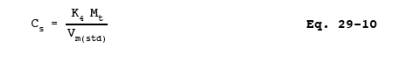
A = Analytical detection limit, g/ml.
B = Liquid volume of digested sample prior to aliquoting for analysis, ml.
C = Stack sample gas volume, dsm3.
Ca1 = Concentration of metal in Analytical Fraction 1A as read from the standard curve, g/ml.
Ca2 = Concentration of metal in Analytical Fraction 2A as read from the standard curve, (g/ml).
Cs = Concentration of a metal in the stack gas, mg/dscm.
D = In-stack detection limit, g/m3.
Fa = Aliquot factor, volume of Sample Fraction 2 divided by volume of Sample Fraction 2A (see Section 8.3.4.)
Fd = Dilution factor (Fd = the inverse of the fractional portion of the concentrated sample in the solution actually used in the instrument to produce the reading Ca1. For example, if a 2 ml aliquot of Analytical Fraction 1A is diluted to 10 ml to place it in the calibration range, Fd = 5).
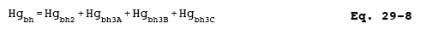
Hgbh = Total mass of Hg collected in the back half of the sampling train, g.
Hgbh2 = Total mass of Hg collected in Sample Fraction 2, g.
Hgbh3(A,B,C) = Total mass of Hg collected separately in Fraction 3A, 3B, or 3C, g.
Hgbhb = Blank correction value for mass of Hg detected in back-half field reagent blanks, g.
Hgfh = Total mass of Hg collected in the front half of the sampling train (Sample Fraction 1), g.
Hgfhb = Blank correction value for mass of Hg detected in front-half field reagent blank, g.
Hgt = Total mass of Hg collected in the sampling train, g.
Mbh = Total mass of each metal (except Hg) collected in the back half of the sampling train (Sample Fraction 2), g.
Mbhb = Blank correction value for mass of metal detected in back-half field reagent blank, g.
Mfh = Total mass of each metal (except Hg) collected in the front half of the sampling train (Sample Fraction 1), g.
Mfhb = Blank correction value for mass of metal detected in front-half field reagent blank, g.
Mt = Total mass of each metal (separately stated for each metal) collected in the sampling train, g.
Mt = Total mass of that metal collected in the sampling train, g; (substitute Hgt for Mt
for the Hg calculation).
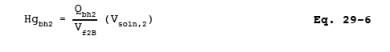
Qbh2 = Quantity of Hg, g, TOTAL in the ALIQUOT of Analytical Fraction 2B selected for digestion and analysis .
NOTE: For example, if a 10 ml aliquot of Analytical Fraction 2B is taken and digested and analyzed (according to Section 11.1.3 and its NOTES Nos. 1 and 2), then calculate and use the total amount of Hg in the 10 ml aliquot for Qbh2.
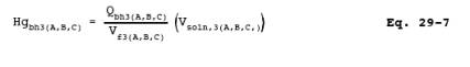
Qbh3(A,B,C) = Quantity of Hg, g, TOTAL, separately, in the ALIQUOT of Analytical Fraction 3A, 3B, or 3C selected for digestion and analysis (see NOTES in Sections 12.7.1 and 12.7.2 describing the quantity "Q" and calculate similarly).
Qfh = Quantity of Hg, g, TOTAL in the ALIQUOT of Analytical Fraction 1B selected for digestion and analysis .
NOTE: For example, if a 10 ml aliquot of Analytical Fraction 1B is taken and digested and analyzed (according to Section 11.1.3 and its NOTES Nos. 1 and 2), then calculate
and use the total amount of Hg in the 10 ml aliquot for Qfh.
Va = Total volume of digested sample solution (Analytical Fraction 2A), ml (see Section 8.3.4.1 or 8.3.4.2, as applicable).
Vf1B = Volume of aliquot of Analytical Fraction 1B analyzed, ml.
NOTE: For example, if a 1 ml aliquot of Analytical Fraction 1B was diluted to 50 ml with 0.15 percent HNO3 as described in Section 11.1.3 to bring it into the proper analytical range, and then 1 ml of that 50-ml was digested according to Section 11.1.3 and analyzed, Vf1B would be 0.02 ml.
Vf2B = Volume of Analytical Fraction 2B analyzed, ml.
NOTE: For example, if 1 ml of Analytical Fraction 2B was diluted to 10 ml with 0.15 percent HNO3 as described in Section 11.1.3 to bring it into the proper analytical range, and then 5 ml of that 10 ml was analyzed, Vf2B would be 0.5 ml.
Vf3(A,B,C) = Volume, separately, of Analytical Fraction 3A, 3B, or 3C analyzed, ml (see previous notes in Sections 12.7.1 and 12.7.2, describing the quantity "V" and calculate similarly).
Vm(std) = Volume of gas sample as measured by the console meter, corrected to dry standard conditions, dscm.
Vsoln,1 = Total volume of digested sample solution (Analytical Fraction 1), ml.
Vsoln,1 = Total volume of Analytical Fraction 1, ml.
Vsoln,2 = Total volume of Sample Fraction 2, ml.
Vsoln,3(A,B,C)= Total volume, separately, of Analytical Fraction 3A, 3B, or 3C, ml.
K4 = 10-3 mg/g.
12.2 Dry Gas Volume. Using the data from this test, calculate Vm(std), the dry gas sample volume at standard conditions as outlined in Section 12.3 of Method 5.
12.3 Volume of Water Vapor and Moisture Content. Using the total volume of condensate collected during the source sampling, calculate the volume of water vapor Vw(std) and the moisture content B>ws of the stack gas. Use Equations 5-2 and 5-3 of Method 5.
12.4 Stack Gas Velocity. Using the data from this test and Equation 2-9 of Method 2, calculate the average stack gas velocity.
12.5 In-Stack Detection Limits. Calculate the in-stack method detection limits shown in Table 29-4 using the conditions described in Section 13.3.1 as follows:
12.6 Metals (Except Hg) in Source Sample.
12.6.1 Analytical Fraction 1A, Front-Half, Metals (except Hg). Calculate separately the amount of each metal collected in Sample Fraction 1 of the sampling train using the following equation:
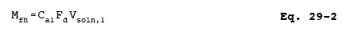
NOTE: If Analytical Fractions 1A and 2A are combined, use proportional aliquots. Then make appropriate changes in Equations 29-2 through 29-4 to reflect this approach.
12.6.2 Analytical Fraction 2A, Back-Half, Metals (except Hg). Calculate separately the amount of each metal collected in Fraction 2 of the sampling train using the following equation:
12.6.3 Total Train, Metals (except Hg). Calculate the total amount of each of the quantified metals collected in the sampling train as follows:
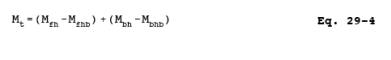
NOTE: If the measured blank value for the front half (Mfhb) is in the range 0.0 to "A" g [where "A" g equals the value determined by multiplying 1.4 g/in.2 times the actual area in in.2 of the sample filter], use Mfhb to correct the emission sample value (Mfh); if Mfhb exceeds "A" g, use the greater of I or II:
I. "A" g.
II. the lesser of (a) Mfhb, or (b) 5 percent of Mfh. If the measured blank value for the back half (Mbhb) is in the range 0.0 to 1 g, use Mbhb to correct the emission sample value (M>bh); if Mbhb exceeds 1 g, use the greater of I or II:
I. 1 g.
II. the lesser of (a) Mbhb, or (b) 5 percent of Mbh.
12.7 Hg in Source Sample.
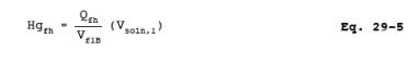
12.7.1 Analytical Fraction 1B; Front-Half Hg. Calculate the amount of Hg collected in the front-half, Sample Fraction 1, of the sampling train by using Equation 29-5:
12.7.2 Analytical Fractions 2B, 3A, 3B, and 3C; Back Half Hg.
12.7.2.1 Calculate the amount of Hg collected in Sample Fraction 2 by using Equation 29-6:
12.7.2.2 Calculate each of the back-half Hg values for Analytical Fractions 3A, 3B, and 3C by using Equation 29-7:
12.7.2.3 Calculate the total amount of Hg collected in the back-half of the sampling train by using Equation 29-8:
12.7.3 Total Train Hg Catch. Calculate the total amount of Hg collected in the sampling train by using Equation 29-9:

NOTE: If the total of the measured blank values (Hgfhb + Hgbhb) is in the range of 0.0 to 0.6 g, then use the total to correct the sample value (Hg>fh + Hgbh); if it exceeds 0.6 g, use the greater of I. or II:
I. 0.6 g.
II. The lesser of (a) (Hgfhb + Hgbhb), or (b) 5 percent of the sample value (Hgfh + Hgbh).
12.8 Individual Metal Concentrations in Stack Gas. Calculate the concentration of each metal in the stack gas (dry basis, adjusted to standard conditions) by using Equation 29-10:
12.9 Isokinetic Variation and Acceptable Results. Same as Method 5, Sections 12.11 and 12.12, respectively.
13.0 Method Performance.
13.1 Range.
For the analysis described and for similar analyses, the ICAP response is linear over several orders of magnitude. Samples containing metal concentrations in the nanograms per ml (ng/ml) to micrograms per ml (g/ml) range in the final analytical solution can be analyzed using this method. Samples containing greater than approximately 50 g/ml As, Cr, or Pb should be diluted to that level or lower for final analysis. Samples containing greater than approximately 20 g/ml of Cd should be diluted to that level before analysis.
13.2 Analytical Detection Limits.
NOTE: See Section 13.3 for the description of in-stack detection limits.
13.2.1 ICAP analytical detection limits for the sample solutions (based on SW-846, Method 6010) are approximately as follows: Sb (32 ng/ml), As (53 ng/ml), Ba (2 ng/ml), Be (0.3 ng/ml), Cd (4 ng/ml), Cr (7 ng/ml), Co (7 ng/ml), Cu (6 ng/ml), Pb (42 ng/ml), Mn (2 ng/ml), Ni (15 ng/ml), P (75 ng/ml), Se (75 ng/ml), Ag (7 ng/ml), Tl (40 ng/ml), and Zn (2 ng/ml). ICP-MS analytical detection limits (based on SW-846, Method 6020) are lower generally by a factor of ten or more. Be is lower by a factor of three. The actual sample analytical detection limits are sample dependent and may vary due to the sample matrix.
13.2.2 The analytical detection limits for analysis by direct aspiration AAS (based on SW-846, Method 7000 series) are approximately as follow: Sb (200 ng/ml), As (2 ng/ml), Ba (100 ng/ml), Be (5 ng/ml), Cd (5 ng/ml), Cr (50 ng/ml), Co (50 ng/ml), Cu (20 ng/ml), Pb (100 ng/ml), Mn (10 ng/ml), Ni (40 ng/ml), Se (2 ng/ml), Ag (10 ng/ml), Tl (100 ng/ml), and Zn (5 ng/ml).
13.2.3 The detection limit for Hg by CVAAS (on the resultant volume of the digestion of the aliquots taken for Hg analyses) can be approximately 0.02 to 0.2 ng/ml, depending upon the type of CVAAS analytical instrument used.
13.2.4 The use of GFAAS can enhance the detection limits compared to direct aspiration AAS as follows: Sb (3 ng/ml), As (1 ng/ml), Be (0.2 ng/ml), Cd (0.1 ng/ml), Cr (1 ng/ml), Co (1 ng/ml), Pb (1 ng/ml), Se (2 ng/ml), and Tl (1 ng/ml).
13.3 In-stack Detection Limits.
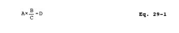
13.3.1 For test planning purposes in-stack detection limits can be developed by using the following information: (1) the procedures described in this method, (2) the analytical detection limits described in Section 13.2 and in SW-846, (3) the normal volumes of 300 ml (Analytical Fraction 1) for the front-half and 150 ml (Analytical Fraction 2A) for the back-half samples, and (4) a stack gas sample volume of 1.25 m3. The resultant in-stack method detection limits for the above set of conditions are presented in Table 29-1 and were calculated by using Eq. 29-1 shown in Section 12.5.
13.3.2 To ensure optimum precision/resolution in the analyses, the target concentrations of metals in the analytical solutions should be at least ten times their respective analytical detection limits. Under certain conditions, and with greater care in the analytical procedure, these concentrations can be as low as approximately three times the respective analytical detection limits without seriously impairing the precision of the analyses. On at least one sample run in the source test, and for each metal analyzed, perform either repetitive analyses, Method of Standard Additions, serial dilution, or matrix spike addition, etc., to document the quality of the data.
13.3.3 Actual in-stack method detection limits are based on actual source sampling parameters and analytical results as described above. If required, the method in-stack detection limits can be improved over those shown in Table 29-1 for a specific test by either increasing the sampled stack gas volume, reducing the total volume of the digested samples, improving the analytical detection limits, or any combination of the three. For extremely low levels of Hg only, the aliquot size selected for digestion and analysis can be increased to as much as 10 ml, thus improving the in-stack detection limit by a factor of ten compared to a 1 ml aliquot size.
13.3.3.1 A nominal one hour sampling run will collect a stack gas sampling volume of about 1.25 m3. If the sampling time is increased to four hours and 5 m3 are collected, the in-stack method detection limits would be improved by a factor of four compared to the values shown in Table 29-1.
13.3.3.2 The in-stack detection limits assume that all of the sample is digested and the final liquid volumes for analysis are the normal values of 300 ml for Analytical Fraction 1, and 150 ml for Analytical Fraction 2A. If the volume of Analytical Fraction 1 is reduced from 300 to 30 ml, the in-stack detection limits for that fraction of the sample would be improved by a factor of ten. If the volume of Analytical Fraction 2A is reduced from 150 to 25 ml, the in-stack detection limits for that fraction of the sample would be improved by a factor of six. Matrix effect checks are necessary on sample analyses and typically are of much greater significance for samples that have been concentrated to less than the normal original sample volume. Reduction of Analytical Fractions 1 and 2A to volumes of less than 30 and 25 ml, respectively, could interfere with the redissolving of the residue and could increase interference by other compounds to an intolerable level.
13.3.3.3 When both of the modifications described in Sections 13.3.3.1 and 13.3.3.2 are used simultaneously on one sample, the resultant improvements are multiplicative. For example, an increase in stack gas volume by a factor of four and a reduction in the total liquid sample digested volume of both Analytical Fractions 1 and 2A by a factor of six would result in an improvement by a factor of twenty-four of the in-stack method detection limit.
13.4 Precision.
The precision (relative standard deviation) for each metal detected in a method development test performed at a sewage sludge incinerator were found to be as follows:
Sb (12.7 percent), As (13.5 percent), Ba (20.6 percent),
Cd (11.5 percent), Cr (11.2 percent), Cu (11.5 percent),
Pb (11.6 percent), P (14.6 percent), Se (15.3 percent),
Tl (12.3 percent), and Zn (11.8 percent).
The precision for Ni was 7.7 percent for another test conducted at a source simulator. Be, Mn, and Ag were not detected in the tests. However, based on the analytical detection limits of the ICAP for these metals, their precisions could be similar to those for the other metals when detected at similar levels.
14.0 Pollution Prevention. [Reserved]
15.0 Waste Management. [Reserved]
16.0 References.
1. Method 303F in Standard Methods for the Examination of Water Wastewater, 15th Edition, 1980. Available from the American Public Health Association, 1015 18th Street N.W., Washington, D.C. 20036.
2. EPA Methods 6010, 6020, 7000, 7041, 7060, 7131, 7421, 7470, 7740, and 7841, Test Methods for Evaluating Solid Waste: Physical/Chemical Methods. SW-846, Third Edition, November 1986, with updates I, II, IIA, IIB and III. Office of Solid Waste and Emergency Response, U. S. Environmental Protection Agency, Washington, D.C. 20460.
3. EPA Method 200.7, Code of Federal Regulations, Title 40, Part 136, Appendix C. July 1, 1987.
4. EPA Methods 1 through 5, Code of Federal Regulations, Title 40, Part 60, Appendix A, July 1, 1991.
5. EPA Method 101A, Code of Federal Regulations, Title 40, Part 61, Appendix B, July 1, 1991.
17.0 Tables, Diagrams, flowcharts, and Validation Data.
TABLE 29-1. IN-STACK METHOD DETECTION LIMITS (g/m>3) FOR THE FRONT-HALF, THE BACK-HALF, AND THE TOTAL SAMPLING TRAIN USING ICAP, GFAAS, AND CVAAS.
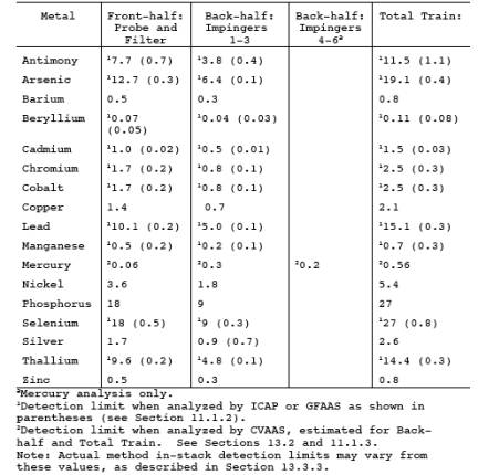
TABLE 29-2. RECOMMENDED WAVELENGTHS FOR ICAP ANALYSIS

TABLE 29-3. APPLICABLE TECHNIQUES, METHODS AND MINIMIZATION OF INTERFERENCES FOR AAS ANALYSIS.
1Refer to EPA publication SW-846 (Reference 2 in Section 16.0).
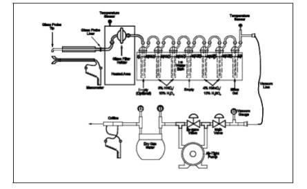
Figure 29-2a. Sample Recovery Scheme.
Figure 29-2b. Sample Recovery Scheme.
Figure 29-3. Sample Preparation and Analysis Scheme.
- Analytical
- Ion Chromatography
- Gas Chromatography
- Gravimetrics
- Ash Resistivity
- Inks/Coatings
- Scrubber Stoichiometry
- Titrations
- Mercury Sorbent Trap
- Engineering
- Express Products
- Rental Instruments
- MET80 Mercury Monitor
- Continuous Emission Monitors
- Gas Sampling Equipment
- Mobile Power Supply
Our Resources
- Technical Resources