- Home
- Careers
- Contact
- About
-
Who we are and what we do. -
Press releases, announcements, and notable corporate information. -
We are looking for a few A people. -
We have over 40 years of innovation to create value for our customers. -
We aim to be the highest value provider of every product and service we offer. -
An easy guide to Probe fundamentals.
-
- Services
-
In additional to the analytical results we normally include an expert analysts summary.
We use our decades of experience to help you better understand your data. -
CleanAir can insures that the project goals and testing are objectives are met.
-
We can ship what you need today. It will work. You get a company of experts when you rent from CleanAir. - Thermal Performance
-
- Rental
-
Our factory reconditioning experts work to make old as good as new. -
CleanAir can provide the services required to care of your emissions measurement or power measurement instruments, no matter the age, model or manufacturer.
-
We deliver rental, emergency, or supplemental instruments and onsite services quickly, with minimal operational interruptions .
-
- Products
Featured Product

UL Listed Mobile Temporary Power
Look professional. Don't risk a OSHA fine, or worse causing your customer to get an OSHA or MSHA fine by using an unsafe mobile power distribution system. The CleanAir Temporary Power cart is UL listed! Read more... -
Reference
-
Overviews of products and services -
Learn about our companies and business -
Detailed technical information about the functioning of our products -
Guides and instructions on proper installation and service -
Guides and instructions on proper installation and service -
Drawings, configuration, materials, and limits useful for the planning and layout.
-
CleanAir's reference of video content -
Publications addressing an issue or topic
-
- Site Map
 Express
 FTIR
FTIR Mercury
 Emission Sampling Equipment
 Instrument Rental
EPA Methods List with Links
US EPA Method 25C - Determination Of Nonmethane Organic Compounds (Nmoc) In Landfill Gases
NOTE: This method does not include all of the specifications (e.g., equipment and supplies) and procedures (e.g., sampling and analytical) essential to its performance. Some material is incorporated by reference from other methods in this part. Therefore, to obtain reliable results, persons using this method should also have a thorough knowledge of EPA Method 25.
1.0 Scope and Application.
1.1 Analytes.
| Analyte | CAS No. |
|---|---|
| Nonmethane organic compounds (NMOC) | No CAS number assigned |
1.2 Applicability.
This method is applicable to the sampling and measurement of NMOC as carbon in landfill gases (LFG).
1.3 Data Quality Objectives.
Adherence to the requirements of this method will enhance the quality of the data obtained from air pollutant sampling methods.
2.0 Summary of Method.
2.1 A sample Probe that has been perforated at one end is driven or augured to a depth of 0.9 m (3 ft) below the bottom of the landfill cover. A sample of the landfill gas is extracted with an evacuated cylinder. The NMOC content of the gas is determined by injecting a portion of the gas into a gas chromatographic column to separate the NMOC from carbon monoxide (CO), carbon dioxide (CO2), and methane (CH4); the NMOC are oxidized to CO2, reduced to CH4, and measured by a flame ionization detector (FID). In this manner, the variable response of the FID associated with different types of organics is eliminated.
3.0 Definitions. [Reserved]
4.0 Interferences. [Reserved]
5.0 Safety.
5.1 Since this method is complex, only experienced personnel should perform this test. LFG contains methane, therefore explosive mixtures may exist on or near the landfill. It is advisable to take appropriate safety precautions when testing landfills, such as refraining from smoking and installing explosion-proof equipment.
6.0 Equipment and Supplies.
6.1 Sample Probe.
Stainless steel, with the bottom third perforated. The sample Probe must be capped at the bottom and must have a threaded cap with a sampling attachment at the top. The sample Probe must be long enough to go through and extend no less than 0.9 m (3 ft) below the landfill cover. If the sample Probe is to be driven into the landfill, the bottom cap should be designed to facilitate driving the Probe into the landfill.
6.2 Sampling Train.
6.2.1 Rotameter with flow Control Valve. Capable of measuring a sample flow rate of 100 ± 10 ml/min. The control valve must be made of stainless steel.
6.2.2 Sampling Valve. Stainless steel.
6.2.3 Pressure Gauge. U-tube mercury manometer, or equivalent, capable of measuring pressure to within 1 mm Hg (0.5 in H20) in the range of 0 to 1,100 mm Hg (0 to 590 in H2O).
6.2.4 Sample Tank. Stainless steel or aluminum cylinder, equipped with a stainless steel sample tank valve.
6.3 Vacuum pump.
Capable of evacuating to an absolute pressure of 10 mm Hg (5.4 in H2O).
6.4 Purging pump.
Portable, explosion proof, and suitable for sampling NMOC.
6.5 Pilot Probe Procedure.
The following are needed only if the tester chooses to use the procedure described in Section 8.2.1.
6.5.1 Pilot Probe. tubing of sufficient strength to withstand being driven into the landfill by a post driver and an outside diameter of at least 6 mm (0.25 in.) smaller than the sample Probe. The pilot Probe shall be capped on both ends and long enough to go through the landfill cover and extend no less than 0.9 m (3 ft) into the landfill.
6.5.2 Post Driver and Compressor. Capable of driving the pilot Probe and the sampling Probe into the landfill. The Kitty Hawk portable post driver has been found to be acceptable.
6.6 Auger Procedure.
The following are needed only if the tester chooses to use the procedure described in Section 8.2.2.
6.6.1 Auger. Capable of drilling through the landfill cover and to a depth of no less than 0.9 m (3 ft) into the landfill.
6.6.2 Pea Gravel.
6.6.3 Bentonite.
6.7 NMOC Analyzer, barometer, Thermometer, and Syringes.
Same as in Sections 6.3.1, 6.3.2, 6.33, and 6.2.10, respectively, of Method 25.
7.0 Reagents and Standards.
7.1 NMOC Analysis.
Same as in Method 25, Section 7.2.
7.2 calibration.
Same as in Method 25, Section 7.4, except omit Section 7.4.3.
7.3 Quality Assurance Audit Samples.
7.3.1 It is recommended, but not required, that a performance audit sample be analyzed in conjunction with the field samples. The audit sample should be in a suitable sample matrix at a concentration similar to the actual field samples.
7.3.2 When making compliance determinations, and upon availability, audit samples may be obtained from the appropriate EPA Regional Office or from the responsible enforcement authority and analyzed in conjunction with the field samples.
NOTE: The responsible enforcement authority should be notified at least 30 days prior to the test date to allow sufficient time for sample delivery.
8.0 Sample Collection, Preservation, Storage, and Transport.
8.1 Sample Tank Evacuation and Leak-Check.
Conduct the sample tank evacuation and leak-check either in the laboratory or the field. Connect the pressure gauge and sampling valve to the sample tank. Evacuate the sample tank to 10 mm Hg (5.4 in H2O) absolute pressure or less. Close the sampling valve, and allow the tank to sit for 30 minutes. The tank is acceptable if no change more than ± 2 mm is noted. Include the results of the leak-check in the test report.
8.2 Sample Probe Installation.
The tester may use the procedure in Section 8.2.1 or 8.2.2.
8.2.1 Pilot Probe Procedure. Use the post driver to drive the pilot Probe at least 0.9 m (3 ft) below the landfill cover. Alternative procedures to drive the Probe into the landfill may be used subject to the approval of the Administrator's designated representative.
8.2.1.1 Remove the pilot Probe and drive the sample Probe into the hole left by the pilot Probe. The sample Probe shall extend at least 0.9 m (3 ft) below the landfill cover and shall protrude about 0.3 m (1 ft) above the landfill cover. Seal around the sampling Probe with bentonite and cap the sampling Probe with the sampling Probe cap.
8.2.2 Auger Procedure. Use an auger to drill a hole to at least 0.9 m (3 ft) below the landfill cover. Place the sample Probe in the hole and backfill with pea gravel to a level 0.6 m (2 ft) from the surface. The sample Probe shall protrude at least 0.3 m (1 ft) above the landfill cover. Seal the remaining area around the Probe with bentonite. Allow 24 hours for the landfill gases to equilibrate inside the augured Probe before sampling.
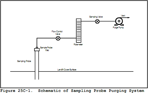
8.3 Sample Train Assembly.
Just before assembling the sample train, measure the sample tank vacuum using the pressure gauge. Record the vacuum, the ambient temperature, and the barometric pressure at this time. Assemble the sampling Probe purging system as shown in Figure 25C-1.
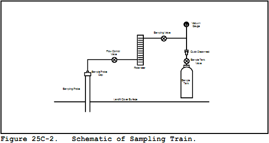
8.4 Sampling Procedure.
Open the sampling valve and use the purge pump and the flow control valve to evacuate at least two sample Probe volumes from the system at a flow rate of 500 ml/min or less. Close the sampling valve and replace the purge pump with the sample tank apparatus as shown in Figure 25C-2. Open the sampling valve and the sample tank valve and, using the flow control valve, sample at a flow rate of 500 ml/min or less until either a constant flow rate can no longer be maintained because of reduced sample tank vacuum or the appropriate composite volume is attained. Disconnect the sampling tank apparatus and pressurize the sample cylinder to approximately 1,060 mm Hg (567 in. H2O) absolute pressure with helium, and record the final pressure. Alternatively, the sample tank may be pressurized in the lab.
8.4.1 The following restrictions apply to compositing samples from different Probe sites into a single cylinder: (1) individual composite samples per cylinder must be of equal volume; this must be verified by recording the flow rate, sampling time, vacuum readings, or other appropriate volume measuring data, (2) individual composite samples must have a minimum volume of 1 liter unless data is provided showing smaller volumes can be accurately measured, and (3) composite samples must not be collected using the final cylinder vacuum as it diminishes to ambient pressure.
8.4.2 Use Method 3C to determine the percent N2 in each cylinder. The presence of N2 indicates either infiltration of ambient air into the landfill gas sample or an inappropriate testing site has been chosen where anaerobic decomposition has not begun. The landfill gas sample is acceptable if the concentration of N2 is less than 20 percent. Alternatively, Method 3C may be used to determine the oxygen content of each cylinder as an air infiltration test. With this option, the oxygen content of each cylinder must be less than 5 percent.
9.0 Quality Control.
9.1 Miscellaneous Quality Control Measures.
| Section | Quality Control Measure | Effect |
|---|---|---|
| 8.4.1 | Verify that landfill gas sample contains less than 20 percent N2 or 5 percent O2 | Ensures that ambient air was not drawn into the landfill gas sample. |
| 10.1, 10.2 | NMOC analyzer initial and daily performance checks | Ensures precision of analytical results |
| 11.1.4 | Audit Sample Analyses | Evaluate analytical technique and instrument calibration |
10.0 Calibration and Standardization.
NOTE: Maintain a record of performance of each item.
10.1 Initial NMOC Analyzer Performance Test.
Same as in Method 25, Section 10.1, except omit the linearity checks for CO2 standards.
10.2 NMOC Analyzer Daily calibration.
10.2.1 NMOC Response Factors. Same as in Method 25, Section 10.2.2.
10.3 Sample Tank Volume.
The volume of the gas sampling tanks must be determined. Determine the tank volumes by weighing them empty and then filled with deionized water; weigh to the nearest 5 g, and record the results. Alternatively, measure the volume of water used to fill them to the nearest 5 ml.
11.0 Analytical Procedures.
11.1 The oxidation, reduction, and measurement of NMOC's
The oxidation, reduction, and measurement of NMOC's is similar to Method 25. Before putting the NMOC analyzer into routine operation, conduct an initial performance test. Start the analyzer, and perform all the necessary functions in order to put the analyzer into proper working order. Conduct the performance test according to the procedures established in Section 10.1. Once the performance test has been successfully completed and the NMOC calibration response factor has been determined, proceed with sample analysis as follows:
11.1.1 Daily Operations and calibration Checks.
Before and immediately after the analysis of each set of samples or on a daily basis (whichever occurs first), conduct a calibration test according to the procedures established in Section 10.2. If the criteria of the daily calibration test cannot be met, repeat the NMOC analyzer performance test (Section 10.1) before proceeding.
11.1.2 Operating Conditions.
Same as in Method 25, Section 11.2.1.
11.1.3 Analysis of Sample Tank.
Purge the sample loop with sample, and then inject the sample. Under the specified operating conditions, the CO2 in the sample will elute in approximately 100 seconds. As soon as the detector response returns to baseline following the CO2 peak, switch the carrier gas flow to backflush, and raise the column oven temperature to 195°C (383°F) as rapidly as possible. A rate of 30°C/min (54°F/min) has been shown to be adequate. Record the value obtained for any measured NMOC. Return the column oven temperature to 85°C (185°F) in preparation for the next analysis. Analyze each sample in triplicate, and report the average as Ctm.
11.2 Audit Sample Analysis.
When the method is used to analyze samples to demonstrate compliance with a source emission regulation, an audit sample, if available, must be analyzed.
11.2.1 Concurrently analyze the audit sample and the compliance samples in the same manner to evaluate the technique of the analyst and the standards preparation.
11.2.2 The same analyst, analytical reagents, and analytical system must be used for the compliance samples and the audit sample. If this condition is met, duplicate auditing of subsequent compliance analyses for the same enforcement agency within a 30-day period is waived. An audit sample set may not be used to validate different sets of compliance samples under the jurisdiction of separate enforcement agencies, unless prior arrangements have been made with both enforcement agencies.
11.3 Audit Sample Results.
11.3.1 Calculate the audit sample concentrations and submit results using the instructions provided with the audit samples.
11.3.2 Report the results of the audit samples and the compliance determination samples along with their identification numbers, and the analyst's name to the responsible enforcement authority. Include this information with reports of any subsequent compliance analyses for the same enforcement authority during the 30-day period.
11.3.3 The concentrations of the audit samples obtained by the analyst must agree within 20 percent of the actual concentration. If the 20-percent specification is not met, reanalyze the compliance and audit samples, and include initial and reanalysis values in the test report.
11.3.4 Failure to meet the 20-percent specification may require retests until the audit problems are resolved. However, if the audit results do not affect the compliance or noncompliance status of the affected facility, the Administrator may waive the reanalysis requirement, further audits, or retests and accept the results of the compliance test. While steps are being taken to resolve audit analysis problems, the Administrator may also choose to use the data to determine the compliance or noncompliance status of the affected facility.
12.0 Data Analysis and Calculations.
NOTE: All equations are written using absolute pressure; absolute pressures are determined by adding the measured barometric pressure to the measured gauge or manometer pressure.
12.1 Nomenclature.
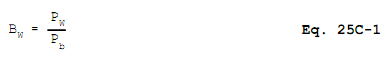
| Bw | = | Moisture content in the sample, fraction. |
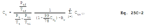
| CN2 | = | Measured N2 concentration, fraction. |
| Ct | = | Calculated NMOC concentration, ppmv C equivalent. |
| Ctm | = | Measured NMOC concentration, ppmv C equivalent. |
| Pb | = | Barometric pressure, mm Hg. |
| Pt | = | Gas sample tank pressure after sampling, but before pressurizing, mm Hg absolute. |
| Ptf | = | Final gas sample tank pressure after pressurizing, mm Hg absolute. |
| Pti | = | Gas sample tank pressure after evacuation, mm Hg absolute. |
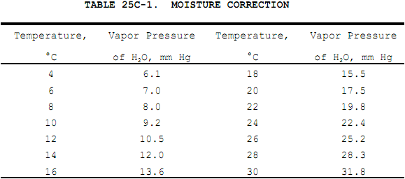
| Pw | = | Vapor pressure of H2O (from Table 25C-1), mm Hg. |
| r | = | Total number of analyzer injections of sample tank during analysis (where j = injection number, 1...r). |
| Tt | = | Sample tank temperature at completion of sampling, °K. |
| Tti | = | Sample tank temperature before sampling, °K. |
| Ttf | = | Sample tank temperature after pressurizing, °K. |
12.2 Water Correction.
Use Table 25C-1 (Section 17.0), the LFG temperature, and barometric pressure at the sampling site to calculate Bw.
12.3 NMOC Concentration.
Use the following equation to calculate the concentration of NMOC for each sample tank.
13.0 Method Performance. [Reserved].
14.0 Pollution Prevention. [Reserved].
15.0 Waste Management. [Reserved].
16.0 References.
- Salo, Albert E., Samuel Witz, and Robert D. MacPhee. Determination of Solvent Vapor Concentrations by Total Combustion Analysis: A Comparison of Infrared with Flame Ionization Detectors. Paper No. 75-33.2. (Presented at the 68th Annual Meeting of the Air Pollution Control Association. Boston, Massachusetts. June 15-20, 1975.) 14 p.
- Salo, Albert E., William L. Oaks, and Robert D. MacPhee. Measuring the Organic Carbon Content of Source Emissions for Air Pollution Control. Paper No. 74-190. (Presented at the 67th Annual Meeting of the Air Pollution Control Association. Denver, Colorado. June 9-13, 1974.) 25 p.
17.0 Tables, Diagrams, flowcharts, and Validation Data.
- Analytical
- Ion Chromatography
- Gas Chromatography
- Gravimetrics
- Ash Resistivity
- Inks/Coatings
- Scrubber Stoichiometry
- Titrations
- Mercury Sorbent Trap
- Engineering
- Express Products
- Rental Instruments
- MET80 Mercury Monitor
- Continuous Emission Monitors
- Gas Sampling Equipment
- Mobile Power Supply
Our Resources
- Technical Resources