- Home
- Careers
- Contact
- About
-
Who we are and what we do. -
Press releases, announcements, and notable corporate information. -
We are looking for a few A people. -
We have over 40 years of innovation to create value for our customers. -
We aim to be the highest value provider of every product and service we offer. -
An easy guide to Probe fundamentals.
-
- Services
-
In additional to the analytical results we normally include an expert analysts summary.
We use our decades of experience to help you better understand your data. -
CleanAir can insures that the project goals and testing are objectives are met.
-
We can ship what you need today. It will work. You get a company of experts when you rent from CleanAir. - Thermal Performance
-
- Rental
-
Our factory reconditioning experts work to make old as good as new. -
CleanAir can provide the services required to care of your emissions measurement or power measurement instruments, no matter the age, model or manufacturer.
-
We deliver rental, emergency, or supplemental instruments and onsite services quickly, with minimal operational interruptions .
-
- Products
Featured Product

UL Listed Mobile Temporary Power
Look professional. Don't risk a OSHA fine, or worse causing your customer to get an OSHA or MSHA fine by using an unsafe mobile power distribution system. The CleanAir Temporary Power cart is UL listed! Read more... -
Reference
-
Overviews of products and services -
Learn about our companies and business -
Detailed technical information about the functioning of our products -
Guides and instructions on proper installation and service -
Guides and instructions on proper installation and service -
Drawings, configuration, materials, and limits useful for the planning and layout.
-
CleanAir's reference of video content -
Publications addressing an issue or topic
-
- Site Map
 Express
 FTIR
FTIR Mercury
 Emission Sampling Equipment
 Instrument Rental
EPA Methods List with Links
US EPA Method 25 - DETERMINATION OF TOTAL GASEOUS NONMETHANE
ORGANIC EMISSIONS AS CARBON
Content [ show/hide ].
1.0 Scope and Application.
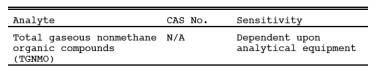
1.1 Analytes.
1.2 Applicability.
1.2.1 This method is applicable for the determination of volatile organic compounds (VOC) (measured as total gaseous non-methane organics (TGNMO) and reported as carbon) in stationary source emissions. This method is not applicable for the determination of organic particulate matter.
1.2.2 This method is not the only method that applies to the measurement of VOC. Costs, logistics, and other practicalities of source testing may make other test methods more desirable for measuring VOC contents of certain effluent streams. Proper judgment is required in determining the most applicable VOC test method. For example, depending upon the molecular composition of the organics in the effluent stream, a totally automated semi-continuous non-methane organics (NMO) analyzer interfaced directly to the source may yield accurate results. This approach has the advantage of providing emission data semi-continuously over an extended time period.
1.2.3 Direct measurement of an effluent with a flame ionization detector (FID) analyzer may be appropriate with prior characterization of the gas stream and knowledge that the detector responds predictably to the organic compounds in the stream. If present, methane (CH4) will, of course, also be measured. The FID can be used under any of the following limited conditions: (1) where only one compound is known to exist; (2) when the organic compounds consist of only hydrogen and carbon; (3) where the relative percentages of the compounds are known or can be determined, and the FID responses to the compounds are known; (4) where a consistent mixture of the compounds exists before and after emission control and only the relative concentrations are to be assessed; or (5) where the FID can be calibrated against mass standards of the compounds emitted (solvent emissions, for example).
1.2.4 Another example of the use of a direct FID is as a screening method. If there is enough information available to provide a rough estimate of the analyzer accuracy, the FID analyzer can be used to determine the VOC content of an uncharacterized gas stream. With a sufficient buffer to account for possible inaccuracies, the direct FID can be a useful tool to obtain the desired results without costly exact determination.
1.2.5 In situations where a qualitative/quantitative analysis of an effluent stream is desired or required, a gas chromatographic FID system may apply. However, for sources emitting numerous organics, the time and expense of this approach will be formidable.
2.0 Summary of Method.
2.1 An emission sample is withdrawn from the stack at a constant rate through a heated filter and a chilled condensate trap by means of an evacuated sample tank. After sampling is completed, the TGNMO are determined by independently analyzing the condensate trap and sample tank fractions and combining the analytical results. The organic content of the condensate trap fraction is determined by oxidizing the NMO to carbon dioxide (CO2) and quantitatively collecting in the effluent in an evacuated vessel; then a portion of the CO2 is reduced to CH4 and measured by an FID. The organic content of the sample tank fraction is measured by injecting a portion of the sample into a gas chromatographic column to separate the NMO from carbon monoxide (CO), CO2, and CH>4; the NMO are oxidized to CO2, reduced to CH4, and measured by an FID. In this manner, the variable response of the FID associated with different types of organics is eliminated.
3.0 Definitions. [Reserved]
4.0 Interferences.
4.1 Carbon Dioxide and Water Vapor.
When carbon dioxide (CO2) and water vapor are present together in the stack, they can produce a positive bias in the sample. The magnitude of the bias depends on the concentrations of CO2 and water vapor. As a guideline, multiply the CO2 concentration, expressed as volume percent, times the water vapor concentration. If this product does not exceed 100, the bias can be considered insignificant. For example, the bias is not significant for a source having 10 percent CO>2 and 10 percent water vapor, but it might be significant for a source having 10 percent CO2and 20 percent water vapor.
4.2. Particulate Matter.
Collection of organic particulate matter in the condensate trap would produce a positive bias. A filter is included in the sampling equipment to minimize this bias.
5.0 Safety.
5.1 Disclaimer. This method may involve hazardous materials, operations, and equipment. This test method may not address all of the safety problems associated with its use. It is the responsibility of the user of this test method to establish appropriate safety and health practices and determine the applicability of regulatory limitations prior to performing this test method.
6.0 Equipment and Supplies.
6.1 Sample Collection.
The sampling system consists of a heated Probe, heated filter, condensate trap, flow control system, and sample tank (see Figure 25-1). The TGNMO sampling equipment can be constructed from commercially available components and components fabricated in a machine shop. The following equipment is required:
6.1.1 Heated Probe. 6.4-mm (1/4-in.) OD stainless steel tubing with a heating system capable of maintaining a gas temperature at the exit end of at least 129C (265F). The Probe shall be equipped with a tenperature sensor at the exit end to monitor the gas temperature. A suitable Probe is shown in Figure 25-1. The probe nozzle is an elbow fitting attached to the front end of the Probe while the tenperature sensor is inserted in the side arm of a tee fitting attached to the rear of the Probe. The Probe is wrapped with a suitable length of high temperature heating tape, and then covered with two layers of glass cloth insulation and one layer of aluminum foil or an equivalent wrapping.
NOTE: If it is not possible to use a heating system for safety reasons, an unheated system with an in-stack filter is a suitable alternative.
6.1.2 filter Holder. 25-mm (15/16-in.) ID Gelman filter holder with 303 stainless steel body and 316 stainless steel support screen with the Viton O-ring replaced by a Teflon O-ring.
6.1.3 filter Heating System.
6.1.3.1 A metal box consisting of an inner and an outer shell separated by insulating material with a heating element in the inner shell capable of maintaining a gas temperature at the filter of 121 ± 3 C (250 ± 5 F). The heating box shall include tenperature sensors to monitor the gas temperature immediately upstream and immediately downstream of the filter.
6.1.3.2 A suitable heating box is shown in Figure 25-2. The outer shell is a metal box that measures 102 mm x 280 mm x 292 mm (4 in. x 11 in. x 11 1/2 in.), while the inner shell is a metal box measuring 76 mm x 229 mm x 241 mm (3 in. x 9 in. x 9 1/2 in.). The inner box is supported by 13-mm (1/2-in.) phenolic rods. The void space between the boxes is filled with ceramic fiber insulation which is sealed in place by means of a silicon rubber bead around the upper sides of the box. A removable lid made in a similar manner, with a 25-mm (1-in.) gap between the parts is used to cover the heating chamber. The inner box is heated with a 250-watt cartridge heater, shielded by a stainless steel shroud. The heater is regulated by a thermostatic temperature controller, which is set to maintain a gas temperature of 121 C (250 F) as measured by the tenperature sensor upstream of the filter.
NOTE: If it is not possible to use a heating system for safety reasons, an unheated system with an in-stack filter is a suitable alternative.
6.1.4 Condensate Trap. 9.5-mm (d-in.) OD 316 stainless steel tubing bent into a U-shape. Exact dimensions are shown in Figure 25-3. The tubing shall be packed with coarse quartz wool, to a density of approximately 0.11 g/cm3 before bending. While the condensate trap is packed with dry ice in the Dewar, an ice bridge may form between the arms of the condensate trap making it difficult to remove the condensate trap. This problem can be prevented by attaching a steel plate between the arms of the condensate trap in the same plane as the arms to completely fill the intervening space.
6.1.5 Valve. Stainless steel control valve for starting and stopping sample flow.
6.1.6 metering Valve. Stainless steel valve for regulating the sample flow rate through the sample train.
6.1.7 Rate meter. Rotameter, or equivalent, capable of measuring sample flow in the range of 60 to 100 cm3/min (0.13 to 0.21 ft3/hr).
6.1.8 Sample Tank. Stainless steel or aluminum tank with a minimum volume of 4 liters (0.14 ft3).
NOTE: Sample volumes greater than 4 liters may be required for sources with low organic concentrations.
6.1.9 Mercury manometer. U-tube manometer or absolute pressure gauge capable of measuring pressure to within 1 mm Hg in the range of 0 to 900 mm.
6.1.10 Vacuum pump. Capable of evacuating to an absolute pressure of 10 mm Hg.
6.2 Condensate Recovery.
The system for the recovery of the organics captured in the condensate trap consists of a heat source, an oxidation catalyst, a non-dispersive infrared (NDIR) analyzer, and an intermediate collection vessel (ICV). Figure 25-4 is a schematic of a typical system. The system shall be capable of proper oxidation and recovery, as specified in Section 10.1.1. The following major components are required:
6.2.1 Heat Source. Sufficient to heat the condensate trap (including Probe) to a temperature of 200 C (390 F). A system using both a heat gun and an electric tube furnace is recommended.
6.2.2 Heat Tape. Sufficient to heat the connecting tubing between the water trap and the oxidation catalyst to 100 C (212 F).
6.2.3 Oxidation Catalyst. A suitable length of 9.5 mm (d-in.) OD Inconel 600 tubing packed with 15 cm (6 in.) of 3.2 mm (c-in.) diameter 19 percent chromia on alumina pellets. The catalyst material is packed in the center of the catalyst tube with quartz wool packed on either end to hold it in place.
6.2.4 Water Trap. Leak-proof, capable of removing moisture from the gas stream.
6.2.5 Syringe Port. A 6.4-mm (1/4-in.) OD stainless steel tee fitting with a rubber septum placed in the side arm.
6.2.6 NDIR Detector. Capable of indicating CO2 concentration in the range of zero to 5 percent, to monitor the progress of combustion of the organic compounds from the condensate trap.
6.2.7 flow-Control Valve. Stainless steel, to maintain the trap conditioning system near atmospheric pressure.
6.2.8 Intermediate Collection Vessel. Stainless steel or aluminum, equipped with a female quick connect. Tanks with nominal volumes of at least 6 liters (0.2 ft3) are recommended.
6.2.9 Mercury manometer. Same as described in Section 6.1.9.
6.2.10 Syringe. 10-ml gas-tight glass syringe equipped with an appropriate needle.
6.2.11 Syringes. 10-l and 50-l liquid injection syringes.
6.2.12 Liquid Sample Injection Unit. 316 Stainless steel U-tube fitted with an injection septum (see Figure 25-7).
6.3 Analysis.
6.3.1 NMO Analyzer.
The NMO analyzer is a gas chromatograph (GC) with back-flush capability for NMO analysis and is equipped with an oxidation catalyst, reduction catalyst, and FID. Figures 25-5 and 25-6 are schematics of a typical NMO analyzer. This semi-continuous GC/FID analyzer shall be capable of: (1) separating CO, CO2, and CH4 from NMO, (2) reducing the CO2 to CH4 and quantifying as CH4, and (3) oxidizing the NMO to CO2, reducing the CO2 to CH4 and quantifying as CH4, according to Section 10.1.2. The analyzer consists of the following major components:
6.3.1.1 Oxidation Catalyst. A suitable length of 9.5-mm (d-in.) OD Inconel 600 tubing packed with 5.1 cm (2 in.) of 19 percent chromia on 3.2-mm (c-in.) alumina pellets. The catalyst material is packed in the center of the tube supported on either side by quartz wool. The catalyst tube must be mounted vertically in a 650 C (1200 F) furnace. Longer catalysts mounted horizontally may be used, provided they can meet the specifications of Section 10.1.2.1.
6.3.1.2 Reduction Catalyst. A 7.6-cm (3-in.) length of 6.4-mm (1/4-in.) OD Inconel tubing fully packed with 100- mesh pure nickel powder. The catalyst tube must be mounted vertically in a 400 C (750 F) furnace.
6.3.1.3 Separation Column(s). A 30-cm (1-ft) length of 3.2-mm (c-in.) OD stainless steel tubing packed with 60/80 mesh Unibeads 1S followed by a 61-cm (2-ft) length of 3.2-mm (c-in.) OD stainless steel tubing packed with 60/80 mesh Carbosieve G. The Carbosieve and Unibeads columns must be baked separately at 200 C (390 F) with carrier gas flowing through them for 24 hours before initial use.
6.3.1.4 Sample Injection System. A single 10-port GC sample injection valve or a group of valves with sufficient ports fitted with a sample loop properly sized to interface with the NMO analyzer (1-cc loop recommended).
6.3.1.5 FID. An FID meeting the following specifications is required:
6.3.1.5.1 Linearity. A linear response (±5 percent) over the operating range as demonstrated by the procedures established in Section 10.1.2.3.
6.3.1.5.2 Range. A full scale range of 10 to 50,000 ppm CH4. Signal attenuators shall be available to produce a minimum signal response of 10 percent of full scale.0
6.3.1.6 Data Recording System. Analog strip chart recorder or digital integration system compatible with the FID for permanently recording the analytical results.
6.3.2 barometer.
Mercury, aneroid, or other barometer capable of measuring atmospheric pressure to within 1 mm Hg.
6.3.3 tenperature sensor.
Capable of measuring the laboratory temperature within 1 C (2 F).
6.3.4 Vacuum pump.
Capable of evacuating to an absolute pressure of 10 mm Hg.
7.0 Reagents and Standards.
7.1 Sample Collection.
The following reagents are required for sample collection:
7.1.1 Dry Ice. Solid CO2, crushed.
7.1.2 Coarse Quartz Wool. 8 to 15 m.
7.1.3 filters. glass fiber filters, without organic binder.
7.2 NMO Analysis.
The following gases are required for NMO analysis:
7.2.1 Carrier Gases. helium (He) and oxygen (O2) containing less than 1 ppm CO2 and less than 0.1 ppm hydrocarbon.
7.2.2 Fuel Gas. Hydrogen (H2), at least 99.999 percent pure.
7.2.3 Combustion Gas. Either air (less than 0.1 ppm total hydrocarbon content) or O2 (purity 99.99 percent or greater), as required by the detector.
7.3 Condensate Analysis.
The following are required for condensate analysis:
7.3.1 Gases. Containing less than 1 ppm carbon.
7.3.1.1 Air.
7.3.1.2 Oxygen.
7.3.2 Liquids. To conform to the specifications established by the Committee on Analytical Reagents of the American Chemical Society.
7.3.2.1 Hexane.
7.3.2.2 Decane.
7.4 calibration.
For all calibration gases, the manufacturer must recommend a maximum shelf life for each cylinder (i.e., the length of time the gas concentration is not expected to change more than ±5 percent from its certified value). The date of gas cylinder preparation, certified organic concentration, and recommended maximum shelf life must be affixed to each cylinder before shipment from the gas manufacturer to the buyer. The following calibration gases are required:
7.4.1 Oxidation Catalyst Efficiency Check calibration Gas. Gas mixture standard with nominal concentration of 1 percent methane in air.
7.4.2 FID Linearity and NMO calibration Gases. Three gas mixture standards with nominal propane concentrations of 20 ppm, 200 ppm, and 3000 ppm, in air.
7.4.3 CO2 calibration Gases. Three gas mixture standards with nominal CO2 concentrations of 50 ppm, 500 ppm, and 1 percent, in air.
NOTE: Total NMO less than 1 ppm required for 1 percent mixture.
7.4.4 NMO Analyzer System Check calibration Gases. Four calibration gases are needed as follows:
7.4.4.1 Propane Mixture. Gas mixture standard containing (nominal) 50 ppm CO, 50 ppm CH4, 1 percent CO2, and 20 ppm C3H>8, prepared in air.
7.4.4.2 Hexane. Gas mixture standard containing (nominal) 50 ppm hexane in air.
7.4.4.3 Toluene. Gas mixture standard containing (nominal) 20 ppm toluene in air.
7.4.4.4 Methanol. Gas mixture standard containing (nominal) 100 ppm methanol in air.
7.5 Quality Assurance Audit Samples.
7.5.1 It is recommended, but not required, that a performance audit sample be analyzed in conjunction with the field samples. The audit sample should be in a suitable sample matrix at a concentration similar to the actual field samples.
7.5.2 When making compliance determinations, and upon availability, audit samples may be obtained from the appropriate EPA Regional Office or from the responsible enforcement authority and analyzed in conjunction with the field samples.
NOTE: The responsible enforcement authority should be notified at least 30 days prior to the test date to allow sufficient time for sample delivery.
8.0 Sample Collection, Preservation, Transport, and Storage.
8.1 Sampling equipment Preparation.
8.1.1 Condensate Trap Cleaning.
Before its initial use and after each use, a condensate trap should be thoroughly cleaned and checked to ensure that it is not contaminated. Both cleaning and checking can be accomplished by installing the trap in the condensate recovery system and treating it as if it were a sample. The trap should be heated as described in Section 11.1.3. A trap may be considered clean when the CO2 concentration in its effluent gas drops below 10 ppm. This check is optional for traps that most recently have been used to collect samples which were then recovered according to the procedure in Section 11.1.3.
8.1.2 Sample Tank Evacuation and Leak-Check.
Evacuate the sample tank to 10 mm Hg absolute pressure or less. Then close the sample tank valve, and allow the tank to sit for 60 minutes. The tank is acceptable if a change in tank vacuum of less than 1 mm Hg is noted. The evacuation and leak-check may be conducted either in the laboratory or the field.
8.1.3 Sampling Train Assembly.
Just before assembly, measure the tank vacuum using a mercury manometer. Record this vacuum, the ambient temperature, and the barometric pressure at this time. Close the sample tank valve and assemble the sampling system as shown in Figure 25-1. Immerse the condensate trap body in dry ice at least 30 minutes before commencing sampling to improve collection efficiency. The point where the inlet tube joins the trap body should be 2.5 to 5 cm (1 to 2 in.) above the top of the dry ice.
8.1.4 Pretest Leak-Check.
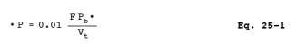
A pretest leak-check is required. Calculate or measure the approximate volume of the sampling train from the Probe tip to the sample tank valve. After assembling the sampling train, plug the Probe tip, and make certain that the sample tank valve is closed. Turn on the vacuum pump, and evacuate the sampling system from the Probe tip to the sample tank valve to an absolute pressure of 10 mm Hg or less. Close the purge valve, turn off the pump, wait a minimum period of 10 minutes, and recheck the indicated vacuum. Calculate the maximum allowable pressure change based on a leak rate of 1 percent of the sampling rate using Equation 25-1, Section 12.2. If the measured pressure change exceeds the allowable, correct the problem and repeat the leak-check before beginning sampling.
8.2 Sample Collection.
8.2.1 Unplug the Probe tip, and place the Probe into the stack such that the Probe is perpendicular to the duct or stack axis; locate the Probe tip at a single preselected point of average velocity facing away from the direction of gas flow. For stacks having a negative static pressure, seal the sample port sufficiently to prevent air in-leakage around the Probe. Set the Probe temperature controller to 129 C (265 F) and the filter temperature controller to 121C (250 F). Allow the Probe and filter to heat for about 30 minutes before purging the sample train.
8.2.2 Close the sample valve, open the purge valve, and start the vacuum pump. Set the flow rate between 60 and 100 cm3/min (0.13 and 0.21 ft3/hr), and purge the train with stack gas for at least 10 minutes.
8.2.3 When the temperatures at the exit ends of the Probe and filter are within the corresponding specified ranges, check the dry ice level around the condensate trap, and add dry ice if necessary. Record the clock time. To begin sampling, close the purge valve and stop the pump. Open the sample valve and the sample tank valve. Using the flow control valve, set the flow through the sample train to the proper rate. Adjust the flow rate as necessary to maintain a constant rate (±10 percent) throughout the duration of the sampling period. Record the sample tank vacuum and flow meter setting at 5-minute intervals. (See Figure 25-8.) Select a total sample time greater than or equal to the minimum sampling time specified in the applicable subpart of the regulations; end the sampling when this time period is reached or when a constant flow rate can no longer be maintained because of reduced sample tank vacuum.
NOTE: If sampling had to be stopped before obtaining the minimum sampling time (specified in the applicable subpart) because a constant flow rate could not be maintained, proceed as follows: After closing the sample tank valve, remove the used sample tank from the sampling train (without disconnecting other portions of the sampling train). Take another evacuated and leak-checked sample tank, measure and record the tank vacuum, and attach the new tank to the sampling train. After the new tank is attached to the sample train, proceed with the sampling until the required minimum sampling time has been exceeded.
8.3 Sample Recovery.
After sampling is completed, close the flow control valve, and record the final tank vacuum; then record the tank temperature and barometric pressure. Close the sample tank valve, and disconnect the sample tank from the sample system. Disconnect the condensate trap at the inlet to the rate meter, and tightly seal both ends of the condensate trap. Do not include the Probe from the stack to the filter as part of the condensate sample.
8.4 Sample Storage and Transport.
Keep the trap packed in dry ice until the samples are returned to the laboratory for analysis. Ensure that run numbers are identified on the condensate trap and the sample tank(s).
9.0 Quality Control.
10.0 Calibration and Standardization.
NOTE: Maintain a record of performance of each item.
10.1 Initial Performance Checks.
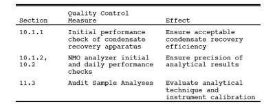
10.1.1 Condensate Recovery Apparatus.
Perform these tests before the system is first placed in operation, after any shutdown of 6 months or more, and after any major modification of the system, or at the frequency recommended by the manufacturer.
10.1.1.1 Carrier Gas and Auxiliary O2 Blank Check. Analyze each new tank of carrier gas or auxiliary O2 with the NMO analyzer to check for contamination. Treat the gas cylinders as non-condensible gas samples, and analyze according to the procedure in Section 11.2.3. Add together any measured CH4, CO, CO2, or NMO. The total concentration must be less than 5 ppm.
10.1.1.2 Oxidation Catalyst Efficiency Check.
10.1.1.2.1 With a clean condensate trap installed in the recovery system or a 1/8" stainless steel connector tube, replace the carrier gas cylinder with the high level methane standard gas cylinder (Section 7.4.1). Set the four-port valve to the recovery position, and attach an ICV to the recovery system. With the sample recovery valve in vent position and the flow-control and ICV valves fully open, evacuate the manometer or gauge, the connecting tubing, and the ICV to 10 mm Hg absolute pressure. Close the flow-control and vacuum pump valves.
10.1.1.2.2 After the NDIR response has stabilized, switch the sample recovery valve from vent to collect. When the manometer or pressure gauge begins to register a slight positive pressure, open the flow-control valve. Keep the flow adjusted such that the pressure in the system is maintained within 10 percent of atmospheric pressure. Continue collecting the sample in a normal manner until the ICV is filled to a nominal gauge pressure of 300 mm Hg. Close the ICV valve, and remove the ICV from the system. Place the sample recovery valve in the vent position, and return the recovery system to its normal carrier gas and normal operating conditions. Analyze the ICV for CO2 using the NMO analyzer; the catalyst efficiency is acceptable if the CO>2 concentration is within 2 percent of the methane standard concentration.
10.1.1.3 System Performance Check. Construct a liquid sample injection unit similar in design to the unit shown in Figure 25-7. Insert this unit into the condensate recovery and conditioning system in place of a condensate trap, and set the carrier gas and auxiliary O2 flow rates to normal operating levels. Attach an evacuated ICV to the system, and switch from system vent to collect. With the carrier gas routed through the injection unit and the oxidation catalyst, inject a liquid sample (see Sections 10.1.1.3.1 to 10.1.1.3.4) into the injection port. Operate the trap recovery system as described in Section 11.1.3. Measure the final ICV pressure, and then analyze the vessel to determine the CO2 concentration. For each injection, calculate the percent recovery according to Section 12.7. Calculate the relative standard deviation for each set of triplicate injections according to Section 12.8. The performance test is acceptable if the average percent recovery is 100 ± 5 percent and the relative standard deviation is less than 2 percent for each set of triplicate injections.
10.1.1.3.1 50 l hexane.
10.1.1.3.2 10 l hexane.
10.1.1.3.3 50 l decane.
10.1.1.3.4 10 l decane.
10.1.2 NMO Analyzer.
Perform these tests before the system is first placed in operation, after any shutdown longer than 6 months, and after any major modification of the system.
10.1.2.1 Oxidation Catalyst Efficiency Check. Turn off or bypass the NMO analyzer reduction catalyst. Make triplicate injections of the high level methane standard (Section 7.4.1). The oxidation catalyst operation is acceptable if the FID response is less than 1 percent of the injected methane concentration.
10.1.2.2 Reduction Catalyst Efficiency Check. With the oxidation catalyst unheated or bypassed and the heated reduction catalyst bypassed, make triplicate injections of the high-level methane standard (Section 7.4.1). Repeat this procedure with both catalysts operative. The reduction catalyst operation is acceptable if the responses under both conditions agree within 5 percent of their average.
10.1.2.3 NMO Analyzer Linearity Check calibration. While operating both the oxidation and reduction catalysts, conduct a linearity check of the analyzer using the propane standards specified in Section 7.4.2. Make triplicate injections of each calibration gas. For each gas (i.e., each set of triplicate injections), calculate the average response factor (area/ppm C) for each gas, as well as and the relative standard deviation (according to Section 12.8). Then calculate the overall mean of the response factor values. The instrument linearity is acceptable if the average response factor of each calibration gas is within 2.5 percent of the overall mean value and if the relative standard deviation gas is less than 2 percent of the overall mean value. Record the overall mean of the propane response factor values as the NMO calibration response factor (RFNMO). Repeat the linearity check using the CO2 standards specified in Section 7.4.3. Make triplicate injections of each gas, and then calculate the average response factor (area/ppm C) for each gas, as well as the overall mean of the response factor values. Record the overall mean of the response factor values as the CO2 calibration response factor (RFCO2). The RFCO2 must be within 10 percent of the RFNMO.
10.1.2.4 System Performance Check. Check the column separation and overall performance of the analyzer by making triplicate injections of the calibration gases listed in Section 7.4.4. The analyzer performance is acceptable if the measured NMO value for each gas (average of triplicate injections) is within 5 percent of the expected value.
10.2 NMO Analyzer Daily calibration.
The following calibration procedures shall be performed before and immediately after the analysis of each set of samples, or on a daily basis, whichever is more stringent:
10.2.1 CO2 Response Factor.
Inject triplicate samples of the high level CO2 calibration gas (Section 7.4.3), and calculate the average response factor. The system operation is adequate if the calculated response factor is within 5 percent of the RFCO2 calculated during the initial performance test (Section 10.1.2.3). Use the daily response factor (DRF>CO2) for analyzer calibration and the calculation of measured CO2 concentrations in the ICV samples.
10.2.2 NMO Response Factors.
Inject triplicate samples of the mixed propane calibration cylinder gas (Section 7.4.4.1), and calculate the average NMO response factor. The system operation is adequate if the calculated response factor is within 10 percent of the RFNMO calculated during the initial performance test (Section 10.1.2.4). Use the daily response factor (DRF>NMO) for analyzer calibration and calculation of NMO concentrations in the sample tanks.
10.3 Sample Tank and ICV Volume.
The volume of the gas sampling tanks used must be determined. Determine the tank and ICV volumes by weighing them empty and then filled with deionized distilled water; weigh to the nearest 5 g, and record the results. Alternatively, measure the volume of water used to fill them to the nearest 5 ml.
11.0 Analytical Procedure.
11.1 Condensate Recovery.
See Figure 25-9. Set the carrier gas flow rate, and heat the catalyst to its operating temperature to condition the apparatus.
11.1.1 Daily Performance Checks. Each day before analyzing any samples, perform the following tests:
11.1.1.1 Leak-Check. With the carrier gas inlets and the sample recovery valve closed, install a clean condensate trap in the system, and evacuate the system to 10 mm Hg absolute pressure or less. Monitor the system pressure for 10 minutes. The system is acceptable if the pressure change is less than 2 mm Hg.
11.1.1.2 System Background Test. Adjust the carrier gas and auxiliary oxygen flow rate to their normal values of 100 cc/min and 150 cc/min, respectively, with the sample recovery valve in vent position. Using a 10-ml syringe, withdraw a sample from the system effluent through the syringe port. Inject this sample into the NMO analyzer, and measure the CO2 content. The system background is acceptable if the CO2concentration is less than 10 ppm.
11.1.1.3 Oxidation Catalyst Efficiency Check. Conduct a catalyst efficiency test as specified in Section 10.1.1.2. If the criterion of this test cannot be met, make the necessary repairs to the system before proceeding.
11.1.2 Condensate Trap CO2 Purge and Sample Tank Pressurization.
11.1.2.1 After sampling is completed, the condensate trap will contain condensed water and organics and a small volume of sampled gas. This gas from the stack may contain a significant amount of CO2 which must be removed from the condensate trap before the sample is recovered. This is accomplished by purging the condensate trap with zero air and collecting the purged gas in the original sample tank.
11.1.2.2 Begin with the sample tank and condensate trap from the test run to be analyzed. Set the four-port valve of the condensate recovery system in the CO2 purge position as shown in Figure 25-9. With the sample tank valve closed, attach the sample tank to the sample recovery system. With the sample recovery valve in the vent position and the flow control valve fully open, evacuate the manometer or pressure gauge to the vacuum of the sample tank. Next, close the vacuum pump valve, open the sample tank valve, and record the tank pressure.
11.1.2.3 Attach the dry ice-cooled condensate trap to the recovery system, and initiate the purge by switching the sample recovery valve from vent to collect position. Adjust the flow control valve to maintain atmospheric pressure in the recovery system. Continue the purge until the CO2 concentration of the trap effluent is less than 5 ppm. CO2concentration in the trap effluent should be measured by extracting syringe samples from the recovery system and analyzing the samples with the NMO analyzer. This procedure should be used only after the NDIR response has reached a minimum level. Using a 10-ml syringe, extract a sample from the syringe port prior to the NDIR, and inject this sample into the NMO analyzer.
11.1.2.4 After the completion of the CO2 purge, use the carrier gas bypass valve to pressurize the sample tank to approximately 1,060 mm Hg absolute pressure with zero
air.
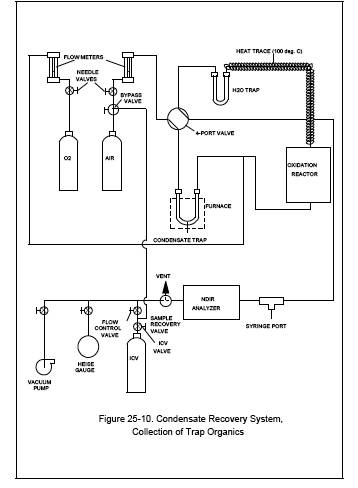
11.1.3 Recovery of the Condensate Trap Sample (See Figure 25-10).
11.1.3.1 Attach the ICV to the sample recovery system. With the sample recovery valve in a closed position, between vent and collect, and the flow control and ICV valves fully open, evacuate the manometer or gauge, the connecting tubing, and the ICV to 10 mm Hg absolute pressure. Close the flow-control and vacuum pump valves.
11.1.3.2 Begin auxiliary oxygen flow to the oxidation catalyst at a rate of 150 cc/min, then switch the four-way valve to the trap recovery position and the sample recovery valve to collect position. The system should now be set up to operate as indicated in Figure 25-10. After the manometer or pressure gauge begins to register a slight positive pressure, open the flow control valve. Adjust the flow-control valve to maintain atmospheric pressure in the system within 10 percent.
11.1.3.3 Remove the condensate trap from the dry ice, and allow it to warm to ambient temperature while monitoring the NDIR response. If, after 5 minutes, the CO2 concentration of the catalyst effluent is below 10,000 ppm, discontinue the auxiliary oxygen flow to the oxidation catalyst. Begin heating the trap by placing it in a furnace preheated to 200 C (390 F). Once heating has begun, carefully monitor the NDIR response to ensure that the catalyst effluent concentration does not exceed 50,000 ppm. Whenever the CO2 concentration exceeds 50,000 ppm, supply auxiliary oxygen to the catalyst at the rate of 150 cc/min. Begin heating the tubing that connected the heated sample box to the condensate trap only after the CO2 concentration falls below 10,000 ppm. This tubing may be heated in the same oven as the condensate trap or with an auxiliary heat source such as a heat gun. Heating temperature must not exceed 200 C (390 F). If a heat gun is used, heat the tubing slowly along its entire length from the upstream end to the downstream end, and repeat the pattern for a total of three times. Continue the recovery until the CO2 concentration drops to less than 10 ppm as determined by syringe injection as described under the condensate trap CO2 purge procedure (Section 11.1.2).
11.1.3.4 After the sample recovery is completed, use the carrier gas bypass valve to pressurize the ICV to approximately 1060 mm Hg absolute pressure with zero air.
11.2 Analysis.
Once the initial performance test of the NMO analyzer has been successfully completed (see Section 10.1.2) and the daily CO2and NMO response factors have been determined (see Section 10.2), proceed with sample analysis as follows:
11.2.1 Operating Conditions. The carrier gas flow rate is 29.5 cc/min He and 2.2 cc/min O2. The column oven is heated to 85 C (185 F). The order of elution for the sample from the column is CO, CH4, CO>2, and NMO.
11.2.2 Analysis of Recovered Condensate Sample. Purge the sample loop with sample, and then inject the sample. Under the specified operating conditions, the CO2 in the sample will elute in approximately 100 seconds. As soon as the detector response returns to baseline following the CO2 peak, switch the carrier gas flow to back-flush, and raise the column oven temperature to 195 C (380 F) as rapidly as possible. A rate of 30 C/min (90 F) has been shown to be adequate. Record the value obtained for the condensible organic material (Ccm) measured as CO2 and any measured NMO. Return the column oven temperature to 85 C (185 F) in preparation for the next analysis. Analyze each sample in triplicate, and report the average Ccm.
11.2.3 Analysis of Sample Tank. Perform the analysis as described in Section 11.2.2, but record only the value measured for NMO (Ctm).
11.3 Audit Sample Analysis.
11.3.1 When the method is used to analyze samples to demonstrate compliance with a source emission regulation, an audit sample, if available, must be analyzed.
11.3.2 Concurrently analyze the audit sample and the compliance samples in the same manner to evaluate the technique of the analyst and the standards preparation.
11.3.3 The same analyst, analytical reagents, and analytical system must be used for the compliance samples and the audit sample. If this condition is met, duplicate auditing of subsequent compliance analyses for the same enforcement agency within a 30-day period is waived. An audit sample set may not be used to validate different sets of compliance samples under the jurisdiction of separate enforcement agencies, unless prior arrangements have been made with both enforcement agencies.
11.4 Audit Sample Results.
11.4.1 Calculate the audit sample concentrations and submit results using the instructions provided with the audit samples.
11.4.2 Report the results of the audit samples and the compliance determination samples along with their identification numbers, and the analyst's name to the responsible enforcement authority. Include this information with reports of any subsequent compliance analyses for the same enforcement authority during the 30-day period.
11.4.3 The concentrations of the audit samples obtained by the analyst must agree within 20 percent of the actual concentration. If the 20-percent specification is not met, reanalyze the compliance and audit samples, and include initial and reanalysis values in the test report.
11.4.4 Failure to meet the 20-percent specification may require retests until the audit problems are resolved. However, if the audit results do not affect the compliance or noncompliance status of the affected facility, the Administrator may waive the reanalysis requirement, further audits, or retests and accept the results of the compliance test. While steps are being taken to resolve audit analysis problems, the Administrator may also choose to use the data to determine the compliance or noncompliance status of the affected facility.
12.0 Data Analysis and Calculations.
Carry out the calculations, retaining at least one extra significant figure beyond that of the acquired data. Round off figures after final calculations. All equations are written using absolute pressure; absolute pressures are determined by adding the measured barometric pressure to the measured gauge or manometer pressure.
12.1 Nomenclature.
C = TGNMO concentration of the effluent, ppm C equivalent.
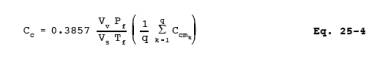
Cc = Calculated condensible organic (condensate trap) concentration of the effluent, ppm C equivalent.
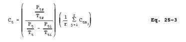
Ccm = Measured concentration (NMO analyzer) for the condensate trap ICV, ppm CO2.
Ct = Calculated noncondensible organic concentration (sample tank) of the effluent, ppm C equivalent.
Ctm = Measured concentration (NMO analyzer) for the sample tank, ppm NMO.
F = Sampling flow rate, cc/min.
L = Volume of liquid injected, l.
M = Molecular weight of the liquid injected, g/gmole.
Mc = TGNMO mass concentration of the effluent, mg C/dsm3.
N = Carbon number of the liquid compound injected
(N = 12 for decane, N = 6 for hexane).
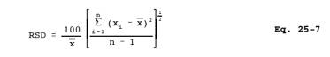
n = Number of data points.
Pf = Final pressure of the intermediate collection vessel, mm Hg absolute.
Pb = Barometric pressure, cm Hg.
Pti = Gas sample tank pressure before sampling, mm Hg absolute.
Pt = Gas sample tank pressure after sampling, but before pressurizing, mm Hg absolute.
Ptf = Final gas sample tank pressure after pressurizing, mm Hg absolute.
q = Total number of analyzer injections of intermediate collection vessel during analysis
(where k = injection number, 1 ... q).
r = Total number of analyzer injections of sample tank during analysis (where j = injection number, 1 ... r).
r = Density of liquid injected, g/cc.
Tf = Final temperature of intermediate collection vessel, K.
Tti = Sample tank temperature before sampling, K.
Tt = Sample tank temperature at completion of sampling, K.
Ttf = Sample tank temperature after pressurizing, K.
V = Sample tank volume, m3.
Vt = Sample train volume, cc.
Vv = Intermediate collection vessel volume, m3.
Vs = Gas volume sampled, dsm3.
xi = Individual measurements.
x = Mean value.
•P = Allowable pressure change, cm Hg.
• = Leak-check period, min.
12.2 Allowable Pressure Change. For the pretest leak-check, calculate the allowable pressure change using Equation 25-1:
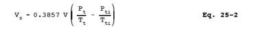
12.3 Sample Volume. For each test run, calculate the gas volume sampled using Equation 25-2:
12.4 Non-condensible Organics. For each sample tank, determine the concentration of non-methane organics (ppm C) using Equation 25-3:
12.5 Condensible Organics. For each condensate trap determine the concentration of organics (ppm C) using Equation 25-4:
12.6 TGNMO Mass Concentration. Determine the TGNMO mass concentration as carbon for each test run, using Equation 25-5:

12.7 Percent Recovery. Calculate the percent recovery for the liquid injections to the condensate recovery and conditioning system using Equation 25-6:
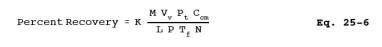
where K = 1.604 (K)(g-mole)(%)/(mm Hg)(ml)(m3)(ppm).
12.8 Relative Standard Deviation. Use Equation 25-7 to calculate the relative standard deviation (RSD) of percent recovery and analyzer linearity.
13.0 Method Performance.
13.1 Range. The minimum detectable limit of the method has been determined to be 50 parts per million by volume (ppm). No upper limit has been established.
14.0 Pollution Prevention. [Reserved]
15.0 Waste Management. [Reserved]
16.0 References.
1. Salo, A.E., S. Witz, and R.D. MacPhee. Determination of Solvent Vapor Concentrations by Total Combustion Analysis: A Comparison of Infrared with Flame Ionization Detectors. Paper No. 75-33.2. (Presented at the 68th Annual Meeting of the Air Pollution Control Association. Boston, MA. June 15-20, 1975.) 14 p.
2. Salo, A.E., W.L. Oaks, and R.D. MacPhee. Measuring the Organic Carbon Content of Source Emissions for Air Pollution Control. Paper No. 74-190. (Presented at the 67th Annual Meeting of the Air Pollution Control Association. Denver, CO. June 9-13, 1974.) 25 p.
17.0 Tables, Diagrams, flowcharts, and Validation Data.
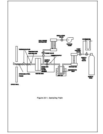
Figure 25-2. Out-of-stack filter Box
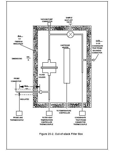
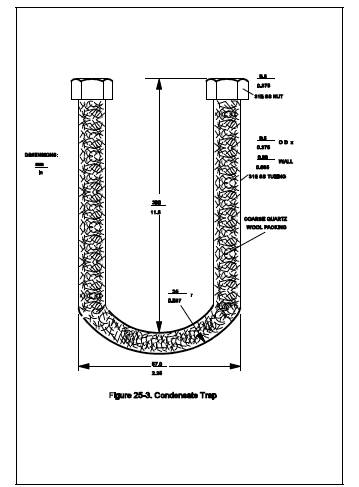
Figure 25-4. Condensate Recovery System
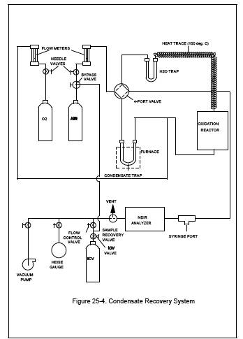
Figure 25-5. Simplified Schematic of Nonmethane Organic (NMO) Analyzer
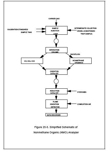
Figure 25-6. Nonmethane Organic Analyzer (NMO)
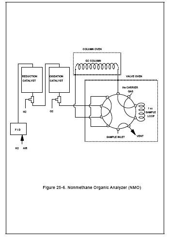
Figure 25-7. Liquid Sample Injection Unit
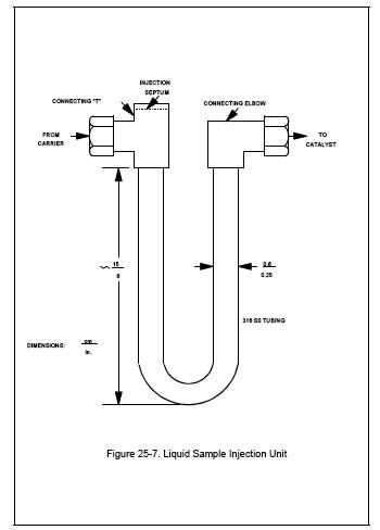
Figure 25-8. Example Field Data Form
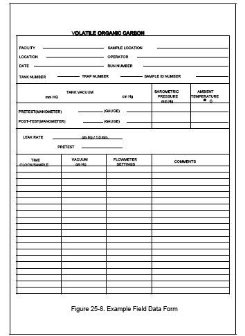
Figure 25-9. Condensate Recovery System, CO2 Purge
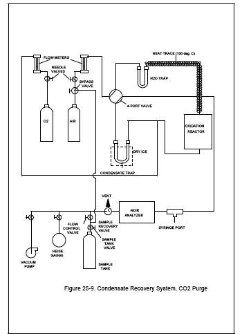
Figure 25-10. Condensate Recovery System,
- Analytical
- Ion Chromatography
- Gas Chromatography
- Gravimetrics
- Ash Resistivity
- Inks/Coatings
- Scrubber Stoichiometry
- Titrations
- Mercury Sorbent Trap
- Engineering
- Express Products
- Rental Instruments
- MET80 Mercury Monitor
- Continuous Emission Monitors
- Gas Sampling Equipment
- Mobile Power Supply
Our Resources
- Technical Resources