Making the World a Better Place .
- Home
- About
-
Who we are and what we do. -
Press releases, announcements, and notable corporate information. -
We are looking for a few A people. -
We have over 40 years of innovation to create value for our customers. -
We aim to be the highest value provider of every product and service we offer. -
An easy guide to Probe fundamentals.
-
- Services
-
In additional to the analytical results we normally include an expert analysts summary.
We use our decades of experience to help you better understand your data. -
CleanAir can insures that the project goals and testing are objectives are met.
-
We can ship what you need today. It will work. You get a company of experts when you rent from CleanAir. - Thermal Performance
-
- Rental
-
Our factory reconditioning experts work to make old as good as new. -
CleanAir can provide the services required to care of your emissions measurement or power measurement instruments, no matter the age, model or manufacturer.
-
We deliver rental, emergency, or supplemental instruments and onsite services quickly, with minimal operational interruptions .
-
- Products
Featured Product

UL Listed Mobile Temporary Power
Look professional. Don't risk a OSHA fine, or worse causing your customer to get an OSHA or MSHA fine by using an unsafe mobile power distribution system. The CleanAir Temporary Power cart is UL listed! Read more... - Careers
-
Reference
-
Overviews of products and services -
Learn about our companies and business -
Detailed technical information about the functioning of our products -
Guides and instructions on proper installation and service -
Guides and instructions on proper installation and service -
Drawings, configuration, materials, and limits useful for the planning and layout.
-
CleanAir's reference of video content -
Publications addressing an issue or topic
-
 Express
 FTIR
FTIR Mercury
 Emission Sampling Equipment
 Instrument Rental
EPA Methods List with Links
Method 15 - Determination Of Hydrogen Sulfide, Carbonyl Sulfide, And Carbon Disulfide Emissions From Stationary Sources
NOTE: This method is not inclusive with respect to specifications (e.g., equipment and supplies) and procedures (e.g., sampling and analytical) essential to its performance. Some material is incorporated by reference from other methods in this part. Therefore, to obtain reliable results, persons using this method should have a thorough knowledge of gas chromatography techniques.
Content [ show/hide ].1.0 Scope and Application.
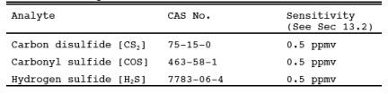
1.1 Analytes.
1.2 Applicability.
1.2.1 This method applies to the determination of emissions of reduced sulfur compounds from tail gas control units of sulfur recovery plants, H2S in fuel gas for fuel gas combustion devices, and where specified in other applicable subparts of the regulations.
1.2.2 The method described below uses the principle of gas chromatographic (GC) separation and flame photometric detection (FPD). Since there are many systems or sets of operating conditions that represent useable methods for determining sulfur emissions, all systems which employ this principle, but differ only in details of equipment and operation, may be used as alternative methods, provided that the calibration precision and sample-line loss criteria are met.
1.3 Data Quality Objectives.
Adherence to the requirements of this method will enhance the quality of the data obtained from air pollutant sampling methods.
2.0 Summary of Method.
2.1 A gas sample is extracted from the emission source and diluted with clean dry air (if necessary).
An aliquot of the diluted sample is then analyzed for CS2, COS, and H2S by GC/FPD.
3.0 Definitions. [Reserved]
4.0 Interferences.
4.1 Moisture Condensation.
Moisture condensation in the sample delivery system, the analytical column, or the FPD burner block can cause losses or interferences. This potential is eliminated by heating the Probe, filter box, and connections, and by maintaining the SO2 scrubber in an ice water bath. Moisture is removed in the SO2 scrubber and heating the sample beyond this point is not necessary provided the ambient temperature is above 0 C (32 F). Alternatively, moisture may be eliminated by heating the sample line, and by conditioning the sample with dry dilution air to lower its dew point below the operating temperature of the GC/FPD analytical system prior to analysis.
4.2 Carbon Monoxide (CO) and Carbon Dioxide (CO2).
CO and CO2 have substantial desensitizing effects on the FPD even after 9:1 dilution. (Acceptable systems must demonstrate that they have eliminated this interference by some procedure such as eluting CO and CO2 before any of the sulfur compounds to be measured.) Compliance with this requirement can be demonstrated by submitting chromatograms of calibration gases with and without CO2 in the diluent gas. The CO2 level should be approximately 10 percent for the case with CO2 present. The two chromatograms should show agreement within the precision limits of Section 13.3.
4.3 Elemental Sulfur.
The condensation of sulfur vapor in the sampling system can lead to blockage of the particulate filter. This problem can be minimized by observing the filter for buildup and changing as needed.
4.4 Sulfur Dioxide (SO2).
SO2 is not a specific interferent but may be present in such large amounts that it cannot be effectively separated from the other compounds of interest. The SO2 scrubber described in Section 6.1.3 will effectively remove SO2 from the sample.
4.5 Alkali Mist.
Alkali mist in the emissions of some control devices may cause a rapid increase in the SO2 scrubber pH, resulting in low sample recoveries. Replacing the SO2 scrubber contents after each run will minimize the chances of interference in these cases.
5.0 Safety.
5.1 Disclaimer. This method may involve hazardous materials, operations, and equipment. This test method may not address all of the safety problems associated with its use. It is the responsibility of the user of this test to establish appropriate safety and health practices and determine the applicability of regulatory limitations to performing this test.
6.0 Equipment and Supplies.
6.1 Sample Collection.
See Figure 15-1. The sampling train component parts are discussed in the following sections:
6.1.1 Probe.
The Probe shall be made of Teflon or Teflon-lined stainless steel and heated to prevent moisture condensation. It shall be designed to allow calibration gas to enter the Probe at or near the sample point entry. Any portion of the Probe that contacts the stack gas must be heated to prevent moisture condensation. The Probe described in Section 6.1.1 of Method 16A having a probe nozzle directed away from the gas stream is recommended for sources having particulate or mist emissions. Where very high stack temperatures prohibit the use of Teflon Probe components, glass or quartz-lined Probes may serve as substitutes.
6.1.2 Particulate filter.
50-mm Teflon filter holder and a 1-to 2-micron porosity Teflon filter (available through Savillex Corporation, 5325 Highway 101, Minnetonka, Minnesota 55343). The filter holder must be maintained in a hot box at a temperature of at least 120 C (248 F).
6.1.3 SO2 Scrubber.
Three 300-ml Teflon segment impingers connected in series with flexible, thick-walled, Teflon tubing. (impinger parts and tubing available through Savillex.) The first two impingers contain 100 ml of citrate buffer, and the third impinger is initially dry. The tip of the tube inserted into the solution should be constricted to less than 3-mm (c-in.) ID and should be immersed to a depth of at least 50 cm (2 in.). Immerse the impingers in an ice water bath and maintain near 0 C. The scrubber solution will normally last for a 3-hour run before needing replacement. This will depend upon the effects of moisture and particulate matter on the solution strength and pH. Connections between the Probe, particulate filter, and SO2 scrubber shall be made of Teflon and as short in length as possible. All portions of the Probe, particulate filter, and connections prior to the SO2 scrubber (or alternative point of moisture removal) shall be maintained at a temperature of at least 120 C (248 F).
6.1.4 Sample Line.
Teflon, no greater than 13-mm (1/2-in.) ID. Alternative materials, such as virgin Nylon, may be used provided the line-loss test is acceptable.
6.1.5 sample pump>.
The sample pump> shall be a leakless Teflon-coated diaphragm type or equivalent.
6.2 Analysis.
The following items are needed for sample analysis:
6.2.1 Dilution System.
The dilution system must be constructed such that all sample contacts are made of Teflon, glass, or stainless steel. It must be capable of approximately a 9:1 dilution of the sample.
6.2.2 Gas Chromatograph
(See Figure 15-2). The gas chromatograph must have at least the following components:
6.2.2.1 oven.
Capable of maintaining the separation column at the proper operating temperature ± 1 C.
6.2.2.2 temperature Gauge.
To monitor column oven, detector, and exhaust temperature ± 1 C.
6.2.2.3 flow System.
Gas metering system to measure sample, fuel, combustion gas, and carrier gas flows.
6.2.2.4 Flame Photometric Detector.
6.2.2.4.1 Electrometer.
Capable of full scale amplification of linear ranges of 10-9 to 10-4 amperes full scale.
6.2.2.4.2 Power Supply.
Capable of delivering up to 750 volts.
6.2.2.5 Recorder.
Compatible with the output voltage range of the electrometer.
6.2.2.6 Rotary Gas Valves.
Multiport Teflon-lined valves equipped with sample loop. Sample loop volumes shall be chosen to provide the needed analytical range. Teflon tubing and fittings shall be used throughout to present an inert surface for sample gas. The GC shall be calibrated with the sample loop used for sample analysis.
6.2.2.7 GC Columns.
The column system must be demonstrated to be capable of resolving three major reduced sulfur compounds: H2S, COS, and CS2. To demonstrate that adequate resolution has been achieved, a chromatogram of a calibration gas containing all three reduced sulfur compounds in the concentration range of the applicable standard must be submitted. Adequate resolution will be defined as base line separation of adjacent peaks when the amplifier attenuation is set so that the smaller peak is at least 50 percent of full scale. Base line separation is defined as a return to zero (±5 percent) in the interval between peaks. Systems not meeting this criteria may be considered alternate methods subject to the approval of the Administrator.
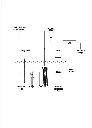
6.3 calibration System
(See Figure 15-3). The calibration system must contain the following components:
6.3.1 flow System.
To measure air flow over permeation tubes within 2 percent. Each flow meter shall be calibrated after each complete test series with a wet-test meter. If the flow-measuring device differs from the wet-test meter by more than 5 percent, the completed test shall be discarded. Alternatively, use the flow data that will yield the lowest flow measurement. calibration with a wet-test meter before a test is optional. flow over the permeation device may also be determined using a soap bubble flow meter.
6.3.2 Constant temperature Bath.
Device capable of maintaining the permeation tubes at the calibration temperature within 0.1 C.
6.3.3 tenperature sensor.
Thermometer or equivalent to monitor bath temperature within 0.1 C.
7.0 Reagents and Standards.
7.1 Fuel. Hydrogen gas (H2). Prepurified grade or better.
7.2 Combustion Gas. Oxygen (O2) or air, research purity or better.
7.3 Carrier Gas. Prepurified grade or better.
7.4 Diluent. Air containing less than 0.5 ppmv total sulfur compounds and less than 10 ppmv each of moisture and total hydrocarbons.
7.5 calibration Gases.
7.5.1 Permeation Devices.
One each of H2S, COS, and CS2, gravimetrically calibrated and certified at some convenient operating temperature. These tubes consist of hermetically sealed FEP Teflon tubing in which a liquefied gaseous substance is enclosed. The enclosed gas permeates through the tubing wall at a constant rate. When the temperature is constant, calibration gases covering a wide range of known concentrations can be generated by varying and accurately measuring the flow rate of diluent gas passing over the tubes. These calibration gases are used to calibrate the GC/FPD system and the dilution system.
7.5.2 Cylinder Gases.
Cylinder gases may be used as alternatives to permeation devices. The gases must be traceable to a primary standard (such as permeation tubes) and not used beyond the certification expiration date.
7.6 Citrate Buffer.
Dissolve 300 g of potassium citrate and 41 g of anhydrous citric acid in 1 liter of water. Alternatively, 284 g of sodium citrate may be substituted for the potassium citrate. Adjust the pH to between 5.4 and 5.6 with potassium citrate or citric acid, as required.
8.0 Sample Collection, Preservation, Transport, and Storage.
8.1 Pretest Procedures.
After the complete measurement system has been set up at the site and deemed to be operational, the following procedures should be completed before sampling is initiated. These procedures are not required, but would be helpful in preventing any problem which might occur later to invalidate the entire test.
8.1.1 Leak-Check.
Appropriate leak-check procedures should be employed to verify the integrity of all components, sample lines, and connections. The following procedure is suggested: For components upstream of the sample pump>, attach the Probe end of the sample line to a manometer or vacuum gauge, start the pump and pull a vacuum greater than 50 mm (2 in.) Hg, close off the pump outlet, and then stop the pump and ascertain that there is no leak for 1 minute. For components after the pump, apply a slight positive pressure and check for leaks by applying a liquid (detergent in water, for example) at each joint. Bubbling indicates the presence of a leak. As an alternative to the initial leak-test, the sample line loss test described in Section 8.3.1 may be performed to verify the integrity of components.
8.1.2 System Performance.
Since the complete system is calibrated at the beginning and end of each day of testing, the precise calibration of each component is not critical. However, these components should be verified to operate properly. This verification can be performed by observing the response of flow meters or of the GC output to changes in flow rates or calibration gas concentrations, respectively, and ascertaining the response to be within predicted limits. If any component or the complete system fails to respond in a normal and predictable manner, the source of the discrepancy should be identified and corrected before proceeding.
8.2 Sample Collection and Analysis.
8.2.1 After performing the calibration procedures outlined in Section 10.0, insert the sampling Probe into the test port ensuring that no dilution air enters the stack through the port. Begin sampling and dilute the sample approximately 9:1 using the dilution system. Note that the precise dilution factor is the one determined in Section 10.4. Condition the entire system with sample for a minimum of 15 minutes before beginning the analysis. Inject aliquots of the sample into the GC/FPD analyzer for analysis. Determine the concentration of each reduced sulfur compound directly from the calibration curves or from the equation for the least-squares line.
8.2.2 If reductions in sample concentrations are observed during a sample run that cannot be explained by process conditions, the sampling must be interrupted to determine if the Probe or filter is clogged with particulate matter. If either is found to be clogged, the test must be stopped and the results up to that point discarded. Testing may resume after cleaning or replacing the Probe and filter. After each run, the Probe and filter shall be inspected and, if necessary, replaced.
8.2.3 A sample run is composed of 16 individual analyses (injects) performed over a period of not less than 3 hours or more than 6 hours.
8.3 Post-Test Procedures.
8.3.1 Sample Line Loss.
A known concentration of H2S at the level of the applicable standard, ±20 percent, must be introduced into the sampling system at the opening of the Probe in sufficient quantities to ensure that there is an excess of sample which must be vented to the atmosphere. The sample must be transported through the entire sampling system to the measurement system in the same manner as the emission samples. The resulting measured concentration is compared to the known value to determine the sampling system loss. For sampling losses greater than 20 percent, the previous sample run is not valid. Sampling losses of 0-20 percent must be corrected by dividing the resulting sample concentration by the fraction of recovery. The known gas sample may be calibration gas as described in Section 7.5. Alternatively, cylinder gas containing H2S mixed in nitrogen and verified according to Section 7.1.4 of Method 16A may be used. The optional pretest procedures provide a good guideline for determining if there are leaks in the sampling system.
8.3.2 Determination of calibration Drift.
After each run, or after a series of runs made within a 24-hour period, perform a partial recalibration using the procedures in Section 10.0. Only H2S (or other permeant) need be used to recalibrate the GC/FPD analysis system and the dilution system. Compare the calibration curves obtained after the runs to the calibration curves obtained under Section 10.3. The calibration drift should not exceed the limits set forth in Section 13.4. If the drift exceeds this limit, the intervening run or runs should be considered invalid. As an option, the calibration data set which gives the highest sample values may be chosen by the tester.
9.0 Quality Control.
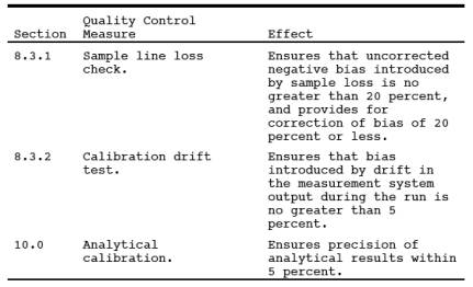
10.0 Calibration and Standardization.
Prior to any sampling run, calibrate the system using the following procedures. (If more than one run is performed during any 24-hour period, a calibration need not be performed prior to the second and any subsequent runs. However, the calibration drift must be determined as prescribed in Section 8.3.2 after the last run is made within the 24-hour period.)
NOTE: This section outlines steps to be followed for use of the GC/FPD and the dilution system. The calibration procedure does not include detailed instructions because the operation of these systems is complex, and it requires an understanding of the individual system being used. Each system should include a written operating manual describing in detail the operating procedures associated with each component in the measurement system. In addition, the operator should be familiar with the operating principles of the components, particularly the GC/FPD. The references in Section 16.0 are recommended for review for this purpose.
10.1 calibration Gas Permeation Tube Preparation.
10.1.1 Insert the permeation tubes into the tube chamber.
Check the bath temperature to assure agreement with the calibration temperature of the tubes within 0.1 C. Allow 24 hours for the tubes to equilibrate. Alternatively, equilibration may be verified by injecting samples of calibration gas at 1-hour intervals. The permeation tubes can be assumed to have reached equilibrium when consecutive hourly samples agree within 5 percent of their mean.
10.1.2 Vary the amount of air flowing over the tubes to produce the desired concentrations for calibrating the analytical and dilution systems.
The air flow across the tubes must at all times exceed the flow requirement of the analytical systems. The concentration in ppmv generated by a tube containing a specific permeant can be calculated using Equation 15-1 in Section 12.2.
10.2 calibration of Analytical System.
Generate a series of three or more known concentrations spanning the linear range of the FPD (approximately 0.5 to 10 ppmv for a 1-ml sample) for each of the three major sulfur compounds. Bypassing the dilution system, inject these standards into the GC/FPD and monitor the responses until three consecutive injections for each concentration agree within 5 percent of their mean. Failure to attain this precision indicates a problem in the calibration or analytical system. Any such problem must be identified and corrected before proceeding.
10.3 calibration Curves.
Plot the GC/FPD response in current (amperes) versus their causative concentrations in ppmv on log-log coordinate graph paper for each sulfur compound. Alternatively, a least-squares equation may be generated from the calibration data using concentrations versus the appropriate instrument response units.
10.4 calibration of Dilution System.
Generate a known concentration of H2S using the permeation tube system. Adjust the flow rate of diluent air for the first dilution stage so that the desired level of dilution is approximated. Inject the diluted calibration gas into the GC/FPD system until the results of three consecutive injections for each dilution agree within 5 percent of their mean. Failure to attain this precision in this step is an indication of a problem in the dilution system. Any such problem must be identified and corrected before proceeding. Using the calibration data for H2S (developed under Section 10.3), determine the diluted calibration gas concentration in ppmv. Then calculate the dilution factor as the ratio of the calibration gas concentration before dilution to the diluted calibration gas concentration determined under this section. Repeat this procedure for each stage of dilution required. Alternatively, the GC/FPD system may be calibrated by generating a series of three or more concentrations of each sulfur compound and diluting these samples before injecting them into the GC/FPD system. These data will then serve as the calibration data for the unknown samples and a separate determination of the dilution factor will not be necessary. However, the precision requirements are still applicable.
11.0 Analytical Procedure.
Sample collection and analysis are concurrent for this method (see Section 8.0).
12.0 Data Analysis and Calculations.
12.1 Nomenclature.
C = Concentration of permeant produced, ppmv.
COS = Carbonyl sulfide concentration, ppmv.
CS2 = Carbon disulfide concentration, ppmv.
d = Dilution factor, dimensionless.
H2S = Hydrogen sulfide concentration, ppmv.
K = 24.04 L/g mole. (Gas constant at 20C and 760 mm Hg)
L = flow rate, L/min, of air over permeant 20C, 760 mm Hg.
M = Molecular weight of the permeant, g/g-mole.
N = Number of analyses performed.
Pr = Permeation rate of the tube, g/min.
12.2 Permeant Concentration. Calculate the concentration generated by a tube containing a specific permeant (see Section 10.1) using the following equation:

12.3 Calculation of SO2 Equivalent. SO2 equivalent will be determined for each analysis made by summing the concentrations of each reduced sulfur compound resolved during the given analysis. The SO2 equivalent is expressed as SO2 in ppmv.

12.4 Average SO2 Equivalent. This is determined using the following equation. Systems that do not remove moisture from the sample but condition the gas to prevent condensation must correct the average SO2 equivalent for the fraction of water vapor present. This is not done under applications where the emission standard is not specified on a dry basis.
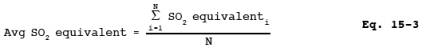
where:
Avg SO2 equivalent = Average SO2 equivalent in ppmv, dry basis.
Average SO2 equivalent i = SO2 in ppmv as determined by Equation 15-2.
13.0 Method Performance.
13.1 Range.
Coupled with a GC system using a 1-ml sample size, the maximum limit of the FPD for each sulfur compound is approximately 10 ppmv. It may be necessary to dilute samples from sulfur recovery plants a hundredfold (99:1), resulting in an upper limit of about 1000 ppmv for each compound.
13.2 Sensitivity.
The minimum detectable concentration of the FPD is also dependent on sample size and would be about 0.5 ppmv for a 1-ml sample.
13.3 calibration Precision.
A series of three consecutive injections of the same calibration gas, at any dilution, shall produce results which do not vary by more than 5 percent from the mean of the three injections.
13.4 calibration Drift.
The calibration drift determined from the mean of three injections made at the beginning and end of any run or series of runs within a 24-hour period shall not exceed 5 percent.
14.0 Pollution Prevention. [Reserved]
15.0 Waste Management. [Reserved]
16.0 References.
1. O'Keeffe, A.E., and G.C. Ortman. "Primary Standards for Trace Gas Analysis." Anal. Chem. 38,760. 1966.
2. Stevens, R.K., A.E. O'Keeffe, and G.C. Ortman. "Absolute calibration of a Flame Photometric Detector to Volatile Sulfur Compounds at Sub-Part-Per-Million Levels." Environmental Science and Technology 3:7. July 1969.
3. Mulik, J.D., R.K. Stevens, and R. Baumgardner. "An Analytical System Designed to Measure Multiple Malodorous Compounds Related to Kraft Mill Activities." Presented at the 12th Conference on Methods in Air Pollution and Industrial Hygiene Studies, University of Southern California, Los Angeles, CA, April 6-8, 1971.
4. Devonald, R.H., R.S. Serenius, and A.D. McIntyre. "Evaluation of the Flame Photometric Detector for Analysis of Sulfur Compounds." Pulp and Paper Magazine of Canada, 73,3. March 1972.
5. Grimley, K.W., W.S. Smith, and R.M. Martin. "The Use of a Dynamic Dilution System in the Conditioning of Stack Gases for Automated Analysis by a Mobile Sampling Van." Presented at the 63rd Annual APCA Meeting in St. Louis, MO. June 14-19, 1970.
6. General Reference. Standard Methods of Chemical Analysis Volume III-A and III-B: Instrumental Analysis. Sixth Edition. Van Nostrand Reinhold Co.
17.0 Tables, Diagrams, flowcharts, and Validation Data.
Figure 15-1. Sampling and Dilution Apparatus.
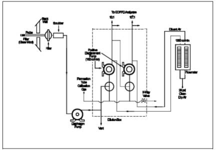
Figure 15-2. Gas Chromatographic Flame Photometric Analyzer.
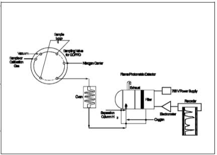
Figure 15-3. Apparatus for Field calibration.