Making the World a Better Place .
- Home
- About
-
Who we are and what we do. -
Press releases, announcements, and notable corporate information. -
We are looking for a few A people. -
We have over 40 years of innovation to create value for our customers. -
We aim to be the highest value provider of every product and service we offer. -
An easy guide to Probe fundamentals.
-
- Services
-
In additional to the analytical results we normally include an expert analysts summary.
We use our decades of experience to help you better understand your data. -
CleanAir can insures that the project goals and testing are objectives are met.
-
We can ship what you need today. It will work. You get a company of experts when you rent from CleanAir. - Thermal Performance
-
- Rental
-
Our factory reconditioning experts work to make old as good as new. -
CleanAir can provide the services required to care of your emissions measurement or power measurement instruments, no matter the age, model or manufacturer.
-
We deliver rental, emergency, or supplemental instruments and onsite services quickly, with minimal operational interruptions .
-
- Products
Featured Product

UL Listed Mobile Temporary Power
Look professional. Don't risk a OSHA fine, or worse causing your customer to get an OSHA or MSHA fine by using an unsafe mobile power distribution system. The CleanAir Temporary Power cart is UL listed! Read more... - Careers
-
Reference
-
Overviews of products and services -
Learn about our companies and business -
Detailed technical information about the functioning of our products -
Guides and instructions on proper installation and service -
Guides and instructions on proper installation and service -
Drawings, configuration, materials, and limits useful for the planning and layout.
-
CleanAir's reference of video content -
Publications addressing an issue or topic
-
 Express
 FTIR
FTIR Mercury
 Emission Sampling Equipment
 Instrument Rental
EPA Methods List with Links
Method 11 - Determination Of Hydrogen Sulfide Content Of Fuel Gas Streams In Petroleum Refineries
Content [ show/hide ].1.0 Scope and Application.
1.1 Analytes.
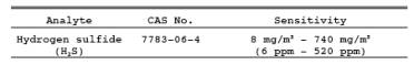
1.2 Applicability.
This method is applicable for the determination of the H2S content of fuel gas streams at petroleum refineries.
1.3 Data Quality Objectives.
Adherence to the requirements of this method will enhance the quality of the data obtained from air pollutant sampling methods.
2.0 Summary of Method.
2.1 A sample is extracted from a source and passed through a series of midget impingers containing a cadmium sulfate (CdSO4) solution; H2S is absorbed, forming cadmium sulfide (CdS). The latter compound is then measured iodometrically.
3.0 Definitions. [Reserved]
4.0 Interferences.
4.1 Any compound that reduces iodine (I2) or oxidizes the iodide ion will interfere in this procedure, provided it is collected in the CdSO4 impingers. Sulfur dioxide in concentrations of up to 2,600 mg/m3 is removed with an impinger containing a hydrogen peroxide (H2O2) solution. Thiols precipitate with H2S. In the absence of H2S, only traces of thiols are collected. When methane- and ethanethiols at a total level of 300 mg/m3 are present in addition to H2S, the results vary from 2 percent low at an H2S concentration of 400 mg/m3 to 14 percent high at an H2S concentration of 100 mg/m3. Carbonyl sulfide at a concentration of 20 percent does not interfere. Certain carbonyl-containing compounds react with iodine and produce recurring end points. However, acetaldehyde and acetone at concentrations of 1 and 3 percent, respectively, do not interfere.
4.2 Entrained H2O2 produces a negative interference equivalent to 100 percent of that of an equimolar quantity of H2S. Avoid the ejection of H2O2 into the CdSO4impingers.
5.0 Safety.
5.1 Disclaimer.
This method may involve hazardous materials, operations, and equipment. This test method may not address all of the safety problems associated with its use. It is the responsibility of the user of this test method to establish appropriate safety and health practices and determine the applicability of regulatory limitations prior to performing this test method.
5.2 Corrosive reagents.
The following reagents are hazardous. Personal protective equipment and safe procedures are useful in preventing chemical splashes. If contact occurs, immediately flush with copious amounts of water for at least 15 minutes. Remove clothing under shower and decontaminate. Treat residual chemical burns as thermal burns.
5.2.1 Hydrogen Peroxide.
Irritating to eyes, skin, nose, and lungs. 30% H2O2 is a strong oxidizing agent. Avoid contact with skin, eyes, and combustible material. Wear gloves when handling.
5.2.2 Hydrochloric Acid. Highly toxic.
Vapors are highly irritating to eyes, skin, nose, and lungs, causing severe damage. May cause bronchitis, pneumonia, or edema of lungs. Exposure to concentrations of 0.13 to 0.2 percent can be lethal in minutes. Will react with metals, producing hydrogen.
6.0 Equipment and Supplies.
6.1 Sample Collection.
The following items are needed for sample collection:
6.1.1 Sampling Line.
Teflon tubing, 6- to 7-mm (1/4- in.) ID, to connect the sampling train to the sampling valve.
6.1.2 impingers.
Five midget impingers, each with 30-ml capacity. The internal diameter of the impinger tip must be 1 mm ± 0.05 mm. The impinger tip must be positioned 4 to 6 mm from the bottom of the impinger.
6.1.3 tubing.
glass or Teflon connecting tubing for the impingers.
6.1.4 Ice Water Bath.
To maintain absorbing solution at a low temperature.
6.1.5 Drying Tube.
Tube packed with 6- to 16- mesh indicating-type silica gel, or equivalent, to dry the gas sample and protect the meter and pump. If the silica gel has been used previously, dry at 175 C (350 F) for 2 hours. New silica gel may be used as received. Alternatively, other types of desiccants (equivalent or better) may be used, subject to approval of the Administrator.
NOTE: Do not use more than 30 g of silica gel. Silica gel adsorbs gases such as propane from the fuel gas stream, and use of excessive amounts of silica gel could result in errors in the determination of sample volume.
6.1.6 Sampling Valve.
Needle valve, or equivalent, to adjust gas flow rate. Stainless steel or other corrosion-resistant material.
6.1.7 Volume meter.
console meter (DGM), sufficiently accurate to measure the sample volume within 2 percent, calibrated at the selected flow rate (about 1.0 liter/min) and conditions actually encountered during sampling. The meter shall be equipped with a tenperature sensor (dial thermometer or equivalent) capable of measuring temperature to within 3 C (5.4 F). The gas meter should have a petcock, or equivalent, on the outlet connector which can be closed during the leak-check. Gas volume for one revolution of the meter must not be more than 10 liters.
6.1.8 Rate Meter.
Rotameter, or equivalent, to measure flow rates in the range from 0.5 to 2 liters/min (1 to 4 ft3/hr).
6.1.9 Graduated Cylinder. 25-ml size.
6.1.10 barometer.
Mercury, aneroid, or other barometer capable of measuring atmospheric pressure to within 2.5 mm Hg (0.1 in. Hg). In many cases, the barometric reading may be obtained from a nearby National Weather Service station, in which case, the station value (which is the absolute barometric pressure) shall be requested and an adjustment for elevation differences between the weather station and the sampling point shall be applied at a rate of minus 2.5 mm Hg (0.1 in Hg) per 30 m (100 ft) elevation increase or vice-versa for elevation decrease.
6.1.11 U-tube manometer. 0- to 30-cm water column, for leak-check procedure.
6.1.12 Rubber Squeeze Bulb. To pressurize train for leak-check.
6.1.13 Tee, Pinchclamp, and Connecting tubing. For leak-check.
6.1.14 pump. Diaphragm pump, or equivalent.
Insert a small surge tank between the pump and rate meter to minimize the pulsation effect of the diaphragm pump on the rate meter. The pump is used for the air purge at the end of the sample run; the pump is not ordinarily used during sampling, because fuel gas streams are usually sufficiently pressurized to force sample gas through the train at the required flow rate. The pump need not be leak-free unless it is used for sampling.
6.1.15 Needle Valve or Critical Orifice.
To set air purge flow to 1 liter/min.
6.1.16 Tube Packed with Active Carbon.
To filter air during purge.
6.1.17 Volumetric Flask.
One 1000-ml.
6.1.18 Volumetric Pipette.
One 15-ml.
6.1.19 Pressure-Reduction Regulator.
Depending on the sampling stream pressure, a pressure-reduction regulator may be needed to reduce the pressure of the gas streamentering the Teflon sample line to a safe level.
6.1.20 Cold Trap.
If condensed water or amine is present in the sample stream, a corrosion-resistant cold trap shall be used immediately after the sample tap. The trap shall not be operated below 0 C (32 F) to avoid condensation of C3 or C4 hydrocarbons.
6.2 Sample Recovery.
The following items are needed for sample recovery:
6.2.1 Sample Container.
Iodine flask, glass-stoppered, 500-ml size.
6.2.2 Volumetric Pipette.
One 50-ml.
6.2.3 Graduated Cylinders.
One each 25-and 250-ml.
6.2.4 Erlenmeyer Flasks.
125-ml.
6.2.5
Wash Bottle.
6.2.6 Volumetric Flasks.
Three 1000-ml.
6.3 Sample Analysis.
The following items are needed for sample analysis:
6.3.1 Flask.
glass-stoppered iodine flask, 500-ml.
6.3.2 Burette.
50-ml.
6.3.3 Erlenmeyer Flask.
125-ml.
6.3.4 Volumetric Pipettes.
One 25-ml; two each 50- and 100-ml.
6.3.5 Volumetric Flasks.
One 1000-ml; two 500-ml.
6.3.6 Graduated Cylinders.
One each 10-and 100-ml.
7.0 Reagents and Standards.
NOTE: Unless otherwise indicated, it is intended that all reagents conform to the specifications established by the Committee on Analytical Reagents of the American Chemical Society, where such specifications are available. Otherwise, use the best available grade.
7.1 Sample Collection.
The following reagents are required for sample collection:
7.1.1 CdSO4 Absorbing Solution.
Dissolve 41 g of 3CdSO48H2O and 15 ml of 0.1 M sulfuric acid in a 1-liter volumetric flask that contains approximately 3/4 liter of water. Dilute to volume with deionized, distilled water. Mix thoroughly. The pH should be 3 ± 0.1. Add 10 drops of Dow-Corning Antifoam B. Shake well before use. This solution is stable for at least one month. If Antifoam B is not used, a more labor-intensive sample recovery procedure is required (see Section 11.2).
7.1.2 Hydrogen Peroxide, 3 Percent.
Dilute 30 percent H2O2 to 3 percent as needed. Prepare fresh daily.
7.1.3 Water.
Deionized distilled to conform to ASTM D 1193-77 or 91, Type 3 (incorporated by reference - see 60.17). The KMnO4 test for oxidizable organic matter may be omitted when high concentrations of organic matter are not expected to be present.
7.2 Sample Recovery.
The following reagents are needed for sample recovery:
7.2.1 Water.
Same as Section 7.1.3.
7.2.2 Hydrochloric Acid (HCl) Solution, 3 M.
Add 240 ml of concentrated HCl (specific gravity 1.19) to 500 ml of water in a 1-liter volumetric flask. Dilute to 1 liter with water. Mix thoroughly.
7.2.3 Iodine (I2) Solution, 0.1 N.
Dissolve 24 g of potassium iodide (KI) in 30 ml of water. Add 12.7 g of resublimed iodine (I2) to the KI solution. Shake the mixture until the I2 is completely dissolved. If possible, let the solution stand overnight in the dark. Slowly dilute the solution to 1 liter with water, with swirling. filter the solution if it is cloudy. Store solution in a brown glass reagent bottle.
7.2.4 Standard I2 Solution, 0.01 N.
Pipette 100.0 ml of the 0.1 N iodine solution into a l-liter volumetric flask, and dilute to volume with water. Standardize daily as in Section 10.2.1. This solution must be protected from light. Reagent bottles and flasks must be kept tightly stoppered.
7.3 Sample Analysis.
The following reagents and standards are needed for sample analysis:
7.3.1 Water.
Same as in Section 7.1.3.
7.3.2 Standard Sodium Thiosulfate Solution, 0.1 N.
Dissolve 24.8 g of sodium thiosulfate pentahydrate (Na2S2O35H2O) or 15.8 g of anhydrous sodium thiosulfate (Na2S2O3) in 1 liter of water, and add 0.01 g of anhydrous sodium carbonate (Na2CO3) and 0.4 ml of chloroform (CHCl3) to stabilize. Mix thoroughly by shaking or by aerating with
nitrogen for approximately 15 minutes, and store in a glass-stoppered, reagent bottle. Standardize as in Section 10.2.2.
7.3.3 Standard Sodium Thiosulfate Solution, 0.01 N.
Pipette 50.0 ml of the standard 0.1 N Na2S2O3solution into a volumetric flask, and dilute to 500 ml with water.
NOTE: A 0.01 N phenylarsine oxide (C6H5AsO) solution may be prepared instead of 0.01 N Na2S2O>3 (see Section 7.3.4).
7.3.4 Standard Phenylarsine Oxide Solution, 0.01 N.
Dissolve 1.80 g of (C6H>5AsO) in 150 ml of 0.3 N sodium hydroxide. After settling, decant 140 ml of this solution into 800 ml of water. Bring the solution to pH 6-7 with 6 N HCl, and dilute to 1 liter with water. Standardize as in Section 10.2.3.
7.3.5 Starch Indicator Solution.
Suspend 10 g of soluble starch in 100 ml of water, and add 15 g of potassium hydroxide (KOH) pellets. Stir until dissolved, dilute with 900 ml of water, and let stand for 1 hour. Neutralize the alkali with concentrated HCl, using an indicator paper similar to Alkacid test ribbon, then add 2 ml of glacial acetic acid as a preservative.
NOTE: Test starch indicator solution for decomposition by titrating with 0.01 N I2 solution, 4 ml of starch solution in 200 ml of water that contains 1 g of KI. If more than 4 drops of the 0.01 N I2solution are required to obtain the blue color, a fresh solution must be prepared.
8.0 Sample Collection, Preservation, Storage, and Transport.
8.1 Sampling Train Preparation.
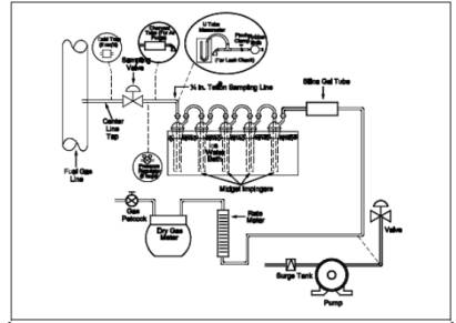
Assemble the sampling train as shown in Figure 11-1, connecting the five midget impingers in series. Place 15 ml of 3 percent H2O2 solution in the first impinger. Leave the second impinger empty. Place 15 ml of the CdSO4 solution in the third, fourth, and fifth impingers. Place the impinger assembly in an ice water bath container, and place water and crushed ice around the impingers. Add more ice during the run, if needed.
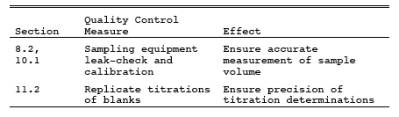
8.2 Leak-Check Procedure.
8.2.1 Connect the rubber bulb and manometer to the first impinger, as shown in Figure 11-1.
Close the petcock on the DGM outlet. Pressurize the train to 25 cm water with the bulb, and close off the tubing connected to the rubber bulb. The train must hold 25 cm water pressure with not more than a 1 cm drop in pressure in a 1-minute interval. Stopcock grease is acceptable for sealing ground glass joints.
8.2.2 If the pump is used for sampling, it is recommended, but not required, that the pump be leak-checked separately, either prior to or after the sampling run.
To leak-check the pump, proceed as follows: Disconnect the drying tube from the impinger assembly. Place a vacuum gauge at the inlet to either the drying tube or the pump, pull a vacuum of 250 mm Hg (10 in. Hg), plug or pinch off the outlet of the flow meter, and then turn off the pump. The vacuum should remain stable for at least 30 seconds. If performed prior to the sampling run, the pump leak-check should precede the leak-check of the sampling train described immediately above; if performed after the sampling run, the pump leak-check should follow the sampling train leak-check.
8.3 Purge connecting line
Purge the connecting line between the sampling valve and the first impinger by disconnecting the line from the first impinger, opening the sampling valve, and allowing process gas to flow through the line for one to two minutes. Then, close the sampling valve, and reconnect the line to 800 the impinger train. Open the petcock on the console meter outlet. Record the initial DGM reading.
8.4 Open the sampling valve
Open the sampling valve, and then adjust the valve to obtain a rate of approximately 1 liter/min (0.035 cfm). Maintain a constant (± 10 percent) flow rate during the test. Record the DGM temperature.
8.5 Sample for at least 10 minutes.
At the end of the sampling time, close the sampling valve, and record the final volume and temperature readings. Conduct a leak-check as described in Section 8.2 above.
8.6 Disconnect the impinger train from the sampling line.
Connect the charcoal tube and the pump as shown in Figure 11-1. Purge the train [at a rate of 1 liter/min (0.035 ft3/min)] with clean ambient air for 15 minutes to ensure that all H2S is removed from the H2O2. For sample recovery, cap the open ends, and remove the impinger train to a clean area that is away from sources of heat. The area should be well lighted, but not exposed to direct sunlight.
8.7 Sample Recovery.
8.7.1 Discard the contents of the H2O2impinger.
Carefully rinse with water the contents of the third, fourth, and fifth impingers into a 500-ml iodine flask.
NOTE: The impingers normally have only a thin film of CdS remaining after a water rinse. If Antifoam B was not used or if significant quantities of yellow CdS remain in the impingers, the alternative recovery procedure in Section 11.2 must be used.
8.7.2
Proceed to Section 11 for the analysis.
9.0 Quality Control.
10.0 Calibration and Standardization.
NOTE: Maintain a log of all calibrations.
10.1 calibration.
Calibrate the sample collection equipment as follows.
10.1.1 console meter.
10.1.1.1 Initial calibration.
The DGM shall be calibrated before its initial use in the field. Proceed as follows: First, assemble the following components in series: Drying tube, needle valve, pump, rotameter, and DGM. Then, leak-check the metering system as follows: Place a vacuum gauge (at least 760 mm Hg) at the inlet to the drying tube, and pull a vacuum of 250 mm Hg (10 in. Hg); plug or pinch off the outlet of the flow meter, and then turn off the pump. The vacuum shall remain stable for at least 30 seconds. Carefully release the vacuum gauge before releasing the flow meter end. Next, calibrate the DGM (at the sampling flow rate specified by the method) as follows: Connect an appropriately sized wet-test meter (e.g., 1 liter per revolution) to the inlet of the drying tube. Make three independent calibration runs, using at least five revolutions of the DGM per run. Calculate the calibration factor, Y (wet-test meter calibration volume divided by the DGM volume, both volumes adjusted to the same reference temperature and pressure), for each run, and average the results. If any Y value deviates by more than 2 percent from the average, the DGM is unacceptable for use. Otherwise, use the average as the calibration factor for subsequent test runs.
10.1.1.2 Post-Test calibration Check.
After each field test series, conduct a calibration check as in Section 10.1.1.1, above, except for the following two variations: (a) three or more revolutions of the DGM may be used and (b) only two independent runs need be made. If the calibration factor does not deviate by more than 5 percent from the initial calibration factor (determined in Section 10.1.1.1), then the DGM volumes obtained during the test series are acceptable. If the calibration factor deviates by more than 5 percent, recalibrate the DGM as in Section 10.1.1.1, and for the calculations, use the calibration factor (initial or recalibration) that yields the lower gas volume for each test run.
10.1.2 tenperature sensors.
Calibrate against mercury-in-glass thermometers.
10.1.3 Rate Meter.
The rate meter need not be calibrated, but should be cleaned and maintained according to the manufacturer's instructions.
10.1.4 barometer.
Calibrate against a mercury barometer.
10.2 Standardization.
10.2.1 Iodine Solution Standardization.
Standardize the 0.01 N I2 solution daily as follows: Pipette 25 ml of the I2 solution into a 125-ml Erlenmeyer flask. Add 2 ml of 3 M HCl. Titrate rapidly with standard 0.01 N Na2S2O3 solution or with 0.01 N C6H5AsO until the solution is light yellow, using gentle mixing. Add four drops of starch indicator solution, and continue titrating slowly until the blue color just disappears. Record the volume of Na2S2O3 solution used, VSI, or the volume of C6H5AsO solution used, V>AI, in ml. Repeat until replicate values agree within 0.05 ml. Average the replicate titration values which agree within 0.05 ml, and calculate the exact normality of the I2 solution using Equation 11-3. Repeat the standardization daily.
10.2.2 Sodium Thiosulfate Solution Standardization.
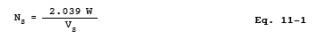
Standardize the 0.1 N Na2S2O3 solution as follows: oven-dry potassium dichromate (K2Cr2O7) at 180 to 200 C (360 to 390 F). To the nearest milligram, weigh 2 g of the dichromate (W). Transfer the dichromate to a 500-ml volumetric flask, dissolve in water, and dilute to exactly 500 ml. In a 500-ml iodine flask, dissolve approximately 3 g of KI in 45 ml of water, then add 10 ml of 3 M Hcl solution. Pipette 50 ml of the dichromate solution into this mixture. Gently swirl the contents of the flask once, and allow it to stand in the dark for 5 minutes. Dilute the solution with 100 to 200 ml of water, washing down the sides of the flask with part of the water. Titrate with 0.1 N Na2S2O3 until the solution is light yellow. Add 4 ml of starch indicator and continue titrating slowly to a green end point. Record the volume of Na2S2O3solution used, VS, in ml. Repeat until replicate values agree within 0.05 ml. Calculate the normality using Equation 11-1. Repeat the standardization each week or after each test series, whichever time is shorter.
10.2.3 Phenylarsine Oxide Solution Standardization.
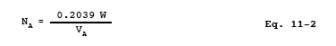
Standardize the 0.01 N C6H5AsO (if applicable) as follows: oven-dry K2Cr2O7 at 180 to 200 C (360 to 390 F). To the nearest milligram, weigh 2 g of the dichromate (W). Transfer the dichromate to a 500-ml volumetric flask, dissolve in water, and dilute to exactly 500 ml. In a 500-ml iodine flask, dissolve approximately 0.3 g of KI in 45 ml of water, then add 10 ml of 3 M HCl. Pipette 5 ml of the dichromate solution into the iodine flask. Gently swirl the contents of the flask once, and allow it to stand in the dark for 5 minutes. Dilute the solution with 100 to 200 ml of water, washing down the sides of the flask with part of the water. Titrate with 0.01 N C6H5AsO until the solution is light yellow. Add 4 ml of starch indicator, and continue titrating slowly to a green end point. Record the volume of C6H5AsO used, VA, in ml. Repeat until replicate analyses agree within 0.05 ml. Calculate the normality using Equation 11-2. Repeat the standardization each week or after each test series, whichever time is shorter.
11.0 Analytical Procedure.
Conduct the titration analyses in a clean area away from direct sunlight.
11.1 Pipette exactly 50 ml of 0.01 N I2 solution into a 125-ml Erlenmeyer flask.
Add 10 ml of 3 M HCl to the solution. Quantitatively rinse the acidified I2 into the iodine flask. Stopper the flask immediately, and shake briefly.
11.2 Use these alternative procedures if Antifoam B was not used or if significant quantities of yellow CdS remain in the impingers.
Extract the remaining CdS from the third, fourth, and fifth impingers using the acidified I2 solution. Immediately after pouring the acidified I2 into an impinger, stopper it and shake for a few moments, then transfer the liquid to the iodine flask. Do not transfer any rinse portion from one impinger to another; transfer it directly to the iodine flask. Once the acidified I2 solution has been poured into any glassware containing CdS, the container must be tightly stoppered at all times except when adding more solution, and this must be done as quickly and carefully as possible. After adding any acidified I2 solution to the iodine flask, allow a few minutes for absorption of the H2S before adding any further rinses. Repeat the I2 extraction until all CdS is removed from the impingers. Extract that part of the connecting glassware that contains visible CdS. Quantitatively rinse all the I2 from the impingers, connectors, and the beaker into the iodine flask using water. Stopper the flask and shake briefly.
11.3
Allow the iodine flask to stand about 30 minutes in the dark for absorption of the H2S into the I2, then complete the titration analysis as outlined in Sections 11.5 and 11.6.
NOTE: Iodine evaporates from acidified I2 solutions. Samples to which acidified I2 has been added may not be stored, but must be analyzed in the time schedule stated above.
11.4 Prepare a blank by adding 45 ml of CdSO4 absorbing solution to an iodine flask.
Pipette exactly 50 ml of 0.01 N I2 solution into a 125-ml Erlenmeyer flask. Add 10 ml of 3 M HCl. Stopper the flask, shake briefly, let stand 30 minutes in the dark, and titrate with the samples.
NOTE: The blank must be handled by exactly the same procedure as that used for the samples.
11.5 Using 0.01 N Na2S2O3 solution (or 0.01 N C6H5AsO, if applicable),
rapidly titrate each sample in an iodine flask using gentle mixing, until solution is light yellow. Add 4 ml of starch indicator solution, and continue titrating slowly until the blue color just disappears. Record the volume of Na2S2O3 solution used, VTT, or the volume of C6H5AsO solution used, VAT, in ml. 11.6 Titrate the blanks in the same manner as the samples. Run blanks each day until replicate values agree within 0.05 ml. Average the replicate titration values which agree within 0.05 ml.
12.0 Data Analysis and Calculations.
Carry out calculations, retaining at least one extra significant figure beyond that of the acquired data. Round off figures only after the final calculation.
12.1 Nomenclature.
CH2S = Concentration of H2S at standard conditions,mg/dscm.
NA = Normality of standard C6H>5AsO solution, g-eq/ liter.
NI = Normality of standard I2 solution, g-eq/liter.
NS = Normality of standard (~0.1 N) Na2S2O3solution, g-eq/liter.
NT = Normality of standard (~0.01 N) Na2S2O3solution, assumed to be 0.1 NS, g-eq/liter.
Pbar = Barometric pressure at the sampling site, mm Hg.
Pstd = Standard absolute pressure, 760 mm Hg.
Tm = Average DGM temperature, K.
Tstd = Standard absolute temperature, 293 K.
VA = Volume of C6H5AsO solution used for standardization, ml.
VAI = Volume of standard C6H5AsO solution used for titration analysis, ml.
VI = Volume of standard I2 solution used for standardization, ml.
VIT = Volume of standard I>2 solution used for titration analysis, normally 50 ml.
Vm = Volume of gas sample at meter conditions, liters.
Vm(std)= Volume of gas sample at standard conditions, liters.
VSI = Volume of ~0.1 N Na2S2O3solution used for standardization, ml.
VT = Volume of standard (~0.01 N) Na2S2O3solution used in standardizing iodine solution (see Section 10.2.1), ml.
VTT = Volume of standard (~0.01 N) Na2S2O3solution used for titration analysis, ml.
W = Weight of K2Cr2O7 used to standardize Na2s2O3 or C6H5AsO solutions, as applicable (see Sections 10.2.2 and 10.2.3), g.
Y = DGM calibration factor.
12.2 Normality of the Standard (~0.1 N) Sodium Thiosulfate Solution.
where:
2.039 = Conversion factor
= (6 g-eq I2/mole K2Cr2O7)(1,000 ml/liter)/(294.2 g K2Cr>2O7/mole)(10 aliquot factor)
12.3 Normality of Standard Phenylarsine Oxide Solution (if applicable).
where:
0.2039 = Conversion factor.
= (6 g-eq I2/mole K2Cr2O7)(1,000 ml/liter)/ (294.2 g K2Cr>2O7/mole)(100 aliquot factor)
12.4 Normality of Standard Iodine Solution.
NOTE: If C6H5AsO is used instead of Na2S2O3, replace NT and VT in Equation 11-3 with NA and VAS, respectively (see Sections 10.2.1 and 10.2.3).
12.5 Dry Gas Volume.
Correct the sample volume measured by the DGM to standard conditions (20 C and 760 mm Hg).
12.6 Concentration of H2S.
Calculate the concentration of H2S in the gas stream at standard conditions using Equation 11-5:
where:
17.04 x 103 = Conversion factor
= (34.07 g/mole H2S)(1,000 liters/m3)(1,000mg/g)/(1,000 ml/liter)(2H2S eq/mole)
NOTE: If C6H5AsO is used instead of NaS2O3, replace NT and VTT in Equation 11-5 with NA and VAT, respectively (see Sections 11.5 and 10.2.3).
13.0 Method Performance.
13.1 Precision.
Collaborative testing has shown the intra-laboratory precision to be 2.2 percent and the interlaboratory precision to be 5 percent.
13.2 Bias.
The method bias was shown to be -4.8 percent when only H2S was present. In the presence of the interferences cited in Section 4.0, the bias was positive at low H2S concentration and negative at higher concentrations. At 230 mg H2S/m>3, the level of the compliance standard, the bias was +2.7 percent. Thiols had no effect on the precision.
14.0 Pollution Prevention. [Reserved]
15.0 Waste Management. [Reserved]
16.0 References.
1. Determination of Hydrogen Sulfide, Ammoniacal Cadmium Chloride Method. API Method 772-54. In: Manual on Disposal of Refinery Wastes, Vol. V: Sampling and Analysis of Waste Gases and Particulate Matter. American Petroleum Institute, Washington, D.C. 1954.
2. Tentative Method of Determination of Hydrogen Sulfide and Mercaptan Sulfur in Natural Gas. Natural Gas Processors Association, Tulsa, OK. NGPA Publication No. 2265-65. 1965.
3. Knoll, J.D., and M.R. Midgett. Determination of Hydrogen Sulfide in Refinery Fuel Gases. Environmental Monitoring Series, Office of Research and Development, USEPA. Research Triangle Park, NC 27711. EPA 600/4-77-007.
4. Scheil, G.W., and M.C. Sharp. Standardization of Method 11 at a Petroleum Refinery. Midwest Research Institute Draft Report for USEPA. Office of Research and Development. Research Triangle Park, NC 27711. EPA Contract No. 68-02-1098. August 1976. EPA 600/4-77-088a (Volume 1) and EPA 600/4-77-088b (Volume 2).
17.0 Tables, Diagrams, flowcharts, and Validation Data.
Figure 11-1. Hydrogen Sulfide Sampling Train.
- Analytical
- Ion Chromatography
- Gas Chromatography
- Gravimetrics
- Ash Resistivity
- Inks/Coatings
- Scrubber Stoichiometry
- Titrations
- Mercury Sorbent Trap
- Engineering
- Express Products
- Rental Instruments
- MET80 Mercury Monitor
- Continuous Emission Monitors
- Gas Sampling Equipment
- Mobile Power Supply
Our Resources
- Technical Resources